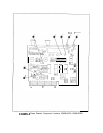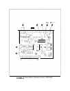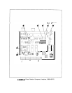
AlOA7
AlOA7
Phase
Lock
Loop
2
(PLL2)
Divider,
Circuit
Description
Reference
Divider
@
A 10 MHz signal derived from the quartz crystal reference is amplified by
Q2
and used to
drive divider U4. The divide by 10 output of U4 drives U16, whose divide by 2 output goes
to the AlOA6 PLL2 Phase Detector. This 500 kHz signal is used as a reference to which
the programmable divide output of the PLL2 Divider is compared. The TTL input on Pl-2
disables the reference divider during sweeps.
Prescaler
GJ
The -18
dBm,
75 to 150 MHz input from AlOA5 PLL2 VCO, is amplified by
Ql
and used to
drive prescaler
UlA
which is a variable-module divider. It divides by 10 if pin 9, “PSW” is
high; it divides by 11 if pin 9 is low.
UlB
is an ECL circuit which contains an ECL to TTL
translator. Pin 7 is the TTL output, which drives gate U9C. U9C is used as a buffer to drive
the multiple of loads on its output; the “CLK” line.
The prescaler should be thought of as a
~10
with the ability to “swallow” input pulses. If
the PSW line is low, in effect one input pulse is lost (swallowed) for each output
(CL10
pulse
produced.
Latches
@
U12, U13, and U14 are latches which store the divider programming number. The number is
clocked into the latches with
LCKl
and LCK2. U14 also latches in SW1 and SW2, which are
sent to AlOA5 PLL2 VCO and
AlOAl
PLLl
VCO.
Direct
Divide
@
U8 and U15 are cascaded dividers whose state outputs are sensed by U9B. The CLK line
from the prescaler clocks U8. When the count reaches 25, the output of
U9B
goes high. This
initiates a divide sequence by J-K flip-flops UlOA and UlOB, which are clocked by CLK. The
Q output of UlOA g
oes high on a count of 27 and low on 29. This signal is output to the
AlOA6 PLL2 Phase Detector. The Q output of UlOA goes low on a count of 27, resetting U8
and U15. When it returns high on 29, the sequence resumes.
U15 is preset to a count of zero and U8 to a count of 0 to 9 depending on input data. Thus, if
U8 is preset to 0, the circuit divides by 29. If preset to 9, the circuit divides by 20.
Since the prescaler has already divided by 10, the 75 to 150 MHz input is divided by numbers
200, 210, . . .
290 according to the BCD digit programming U8. Since the output is locked
to 500 kHz by the phase lock loop, the VCO is programmed from 100 to 145 MHz in 5 MHz
steps.
AlOA7
1


