


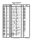
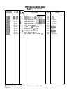

AlOA5
AlOA5
Phase
Lock
Loop
2
(PLL2)
Voltage
Controlled
Oscillator
(VCO),
Circuit
Description
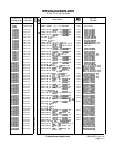
75
to
150
MHz
VCO
@
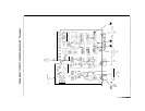
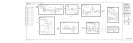
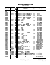
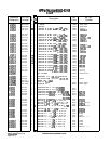
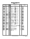
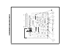
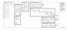
The VCO is a varactor tuned oscillator which tunes 75 to 150 MHz. Varactors
CRl,
CR2,
CR3, and CR4 form a series-tuned resonant circuit with L4 and L5. This series circuit
connects the emitters of
Ql
and
Q2.
Q2 is a common-base amplifier whose load impedance is
made up primarily of L9, R14, and R15. The voltage across the load is coupled to the base of
emitter-follower
Ql,
which drives the series resonant circuit.
Bias
Network/50
kHz
Low-Pass
Filter
@
Transistors Q5 and Q6 and associated components form a filtered -32 V source to bias the
varactor tuning diodes. In the absence of tuning current, the varactor bias is set by R2 to
approximately -17 V. Tuning current from the AlOA8 PLL2 Discriminator passes through
the 50 kHz low-pass filter and acts to pull this bias voltage in a positive direction. Tuning
sensitivity is set by R4, to -10
Mhz/mA.
75
to
150
MHz
Output
Buffer
@
Q4 is a grounded-base amplifier to isolate the VCO from the load circuits. The output of Q4
is filtered, attenuated, and used to drive the AlOA7 PLL2 Divider.
Frequency
Dividers
@
Q3 isolates the VCO from the dividers and develops the required drive voltage. Note that all
of the dividers and gates are ECL with
Vcc
hooked to
+5
V and
VEE
grounded. U3 divides
the VCO frequency by 5; to the range of 15 to 30 MHz. U6C provides isolation. U2 divides
the output by 5; to the range of 3 to 6 MHz. U2 then further divides by 2 and
Ul
divides
the output by 10, to the range of is 0.15 to 0.30 MHz. The output of
Ul
is fed to the
AlOh
PLL2 Discriminator.
Small
Span
Switch
@
U5 functions as a single-pole double-throw switch, controlled by SW2. For frequency spans
greater than n x 5 kHz up to n x 100 kHz, SW2 is TTL high, routing the 3 to 6 MHz signal
from U2 through U5C, U5B, and U5D to the AlOA4 PLL3 Up Converter (n is the harmonic
mixing number). When the frequency span is n x 5 kHz or less, or greater than n x 5 MHz,
SW2 is low, routing the 0.15 to 0.30 MHz signal from
Ul
through U5A and U5D to the PLL3
Up Converter. R33 and R34 shift the TTL levels to ECL levels.
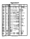
AlOA5
1