


All
YTO
Loop
and
AllA
YTO
Replacement
Note
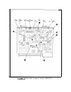
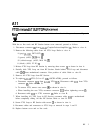
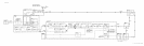
For location of hardware and cables referred to in this procedure, see Figure 1.
With the ac line cords and RF Section bottom cover removed, proceed as follows:
1. Disconnect connector
@
from
AllAl
(Coupler/Isolator/Amplifier)
0.
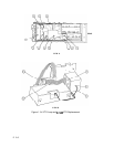
Refer to view A.
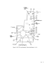
2. Remove the following cables from All YTO Loop. Refer to view A.
8 (gray)
(AllJl,
DET OUT)
@
5 (green) (AllJ3,
20/30
IN)
@
93 (white/orange) (AllJ2, M/N IN)
0
0 (black) (AllJ4, IF IN)
@
3. Release YTO Loop from RF Section by removing three screws
@
as shown in view A.
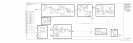
4. Partially slide YTO Loop out from RF Section. Reach behind YTO Loop and disconnect
cable @@ from motherboard connector. Note position of cable. Refer to view B.
5. Remove All YTO Loop from RF Section.
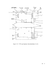
6. To replace
AllA
YTO (2.0 to 6.2 GHz OSCILLATOR), proceed as follows.
a. Disconnect connector @@ from
AllA
YTO
a@.
Disconnect cable @@ from YTO
connector @. Refer to view B.
b. To remove YTO, remove two screws
@
as shown in view A.
c. When installing the new YTO, reconnect connector
a@
before tightening screws
0.
d. Reconnect cable
a@
to YTO connector @. Refer to view B.
7. When installing All YTO Loop in RF Section, reconnect cable @@ to motherboard
before completely sliding All into RF Section. Refer to view B.
8. Secure YTO Loop to RF Section with screws
@
as shown in view A.
9. Reconnect cables and connectors to YTO Loop as removed in steps 1 and 2.
10. Replace bottom cover and ac line cords.
All 1