


Front-Panel Interface and is enabled (pulled low) whenever front-panel key selections indicate
that more than one harmonic board is being swept.
Voltage
Reference
@
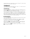
Voltage Reference U7 and associated circuitry provide a stable -7 V dc reference voltage for
both the Sweep Time and Aux Out Offset DACs.
Scan
Test
Circuit
@
The control signal HSWP (High = Sweeping)
is normally pulled low indicating the end of a
sweep by the
A3Al
Trigger in the IF-Display Section. This signal can also be pulled low by
the Scan Test Circuit for the purpose of testing the scan circuitry.
If the scan ramp should exceed
+ll
V, this overvoltage is detected by
UllD
which triggers
one-shot multivibrator U6. U6 generates a 50 ms pulse on the HSWP line. When this pulse
goes low, the Al5 Controller “thinks” that the sweep has ended and performs its update
functions. When the pulse goes high again (after 50 ms), the Al5 Controller “thinks” a new
sweep has begun. This enables the sweep circuitry to function without the IF-Display Section,
or when a circuit malfunction exists, thus aiding troubleshooting.
Scan
Reset
Amplifier
@
The Scan Reset Amplifier supplies negative feedback that holds SCAN OUT (Q12 emitter) at
ground potential during retrace.
For Scan Generator (HP part number 85660-60198): Fixed-gain amplifier U13 amplifies
any potential at its noninverting input, pin 3. During retrace, LSAMPLE is low, and
sample-and-hold device U14 tracks the U13 output, charging C20.
This error voltage at
C20
is divided by R64, R65, and R66, and is summed with the Span
Width DAC output at U12 pin 2. The amplified and inverted output of U12 cancels the
potential at SCAN OUT that produced the error voltage across C20.
When the sweep commences,
HSWP
and LSAMPLE are high. The input to U14 is held on
C20
for the duration of the sweep.
Al6 3