


A6
A6 RF Module Replacement
Note
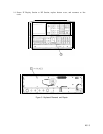
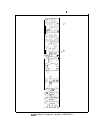
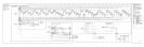
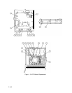
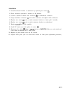
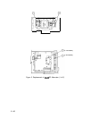
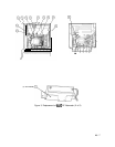
For location of hardware and cables referred to in this procedure, see Figure 1.
Removal
1. Remove ac line cords, separate instrument sections, and remove top, bottom, and right
side covers from RF Section.
2. Remove RF front panel. (See A5 Front Panel Removal procedure in A5 Front Panel
section.)
3. Remove two clips
@)
by removing four screws
0.
4. Remove five cables
@
from A6 PC boards.
5. Remove A6 RF Module PC cover plate by removing six screws
0.
6. Disconnect coaxial cable
@
at point shown.
7. Disconnect two ribbon cables
@
from motherboard.
8. Remove five screws
0.
9. Slide the RF Module out from the mainframe.
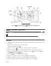
Installation
10. Slide the RF Module into the mainframe; push coaxial cable
@
in slightly so that it does
not get caught on the mainframe.
11. Replace five screws
0.
12. Reconnect two ribbon cables
@
to motherboard.
13. Reconnect coaxial cable
0.
14. Replace A6 RF Module PC cover plate by replacing six screws
0.
15. Replace five cables
@
to A6 PC boards.
16. Replace two clips
@)
by replacing four screws
0.
17. Replace front panel.
18. Replace top, bottom, and side covers, reconnect IF and RF Sections, and reconnect ac line
cords.
A6 1