


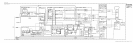

Phase Lock Loop Troubleshooting
If one of the phase-lock error messages appears, a loop has failed. Start the troubleshooting
procedure by determining if the malfunction is dependent on Center Frequency, Frequency
Span, etc. Next, break the suspected loop and measure the power levels as indicated on the
RF Section Analog Block Diagram. Even with the oscillators at the extremes of their ranges,
the power levels must be within the limits indicated. The loop frequencies can be counted and
compared with the programmed frequencies listed by KSR by inserting a tee connector into
the loop.
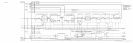
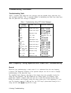
The Lock Indicator Disable jumper
(A12TP2
to
A12TP3)
may be necessary if the keyboard
is locked out. Use the information from the Diagnostic Function and the Start Frequency
Tuning Equations to narrow the fault to a single assembly.
Analog Troubleshooting 7