


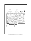
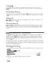
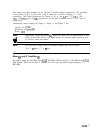
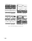
The second and third numbers are the M and N divide numbers respectively. The waveform
at test points 3 and 7, 5 and 6, and 1 and 2 should be as shown in Figures 1, 2, and 3
respectively. The Center Frequencies for Figure la, lb, lc, and
Id
are 3.77 GHz, 3.96
GHz, 4.15 GHz, and 4.34 GHz respectively. The M and N numbers are 20, 21, 22, and 23
respectively.
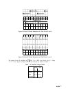
Oscilloscope control settings for Figure 1, Figure 2, and Figure 3 are:
Vertical: 0.1
V/Div
Horizontal: 0.2
psec/Div
Probe:
1O:l
Note
!iil
Waveforms on the M Divider
0
require the M/N VCO be phase-locked at 380
MHz. If the M/N VCO
is not phase-locked, an external signal generator may
be used to locate the failure.
Note
3
All waveform voltage levels are emitter coupled logic (ECL) levels:
-0.9 V
=
high, -1.7 V
=
low.
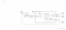
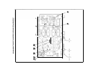
Mixer
(EJ
and IF Amplifier
@
The Mixer inputs are 400 MHz from A7A2 100 MHz VCXO and 355 to 395 MHz from A7A4
M/N Output. When the M and N numbers are the same, the M/N output frequency is
380
MHz.
A7A3
3