


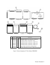

n Schematic Diagram
Replacement Procedures
Replacement procedures are included for use in removing and replacing assemblies for repair.
They are located in the following sections:
w
A5 Front Panel
Front Panel Removal and Repair
w
A6 RF Module
A6 RF Module Replacement
A6Al
Coaxial Switch and A6A17 300 MHz BPF Replacement
A6A2 RF Attenuator Replacement
A6A4 Second Converter Replacement
A6A6 First Converter Replacement
A6A15 3.6 GHz BPF, A6A16 1.5 GHz
LPF, and A6A18 LPF Replacement
n A6A3 Last Converter
A6A3 Last Converter Replacement
H
A6A7 YTX Current
Driver/A6A5
ACLU/A6A8 YTX
A6A5 Amplifier/Coupler/Load Unit
(ACLU) Replacement
A6A7 YTX Current Driver Replacement
A6A8 YTX Replacement
w
A7M/N-Reference
A7 M/N-Reference Replacement
H
A8 Rectifier/A9 Power Line Module
RF Section Internal Fuse Replacement
Transformer Replacement
Power Transistor Replacement
n All YTO Loop
All YTO Loop and
AllA3
YTO
(2.0 to 6.2 GHz Oscillator) Replacement
n Al7 Positive Regulator
RF Section Internal Fuse Replacement
n Al8 Negative Regulator
RF Section Internal Fuse Replacement
2 General Information