


AlOA3
AlOA3
Phase
Lock
Loop
1
(PLLI)
IF,
Circuit
Description
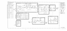
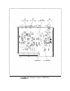
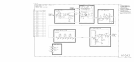
AlOA3 functions to mix the output of A10A4 (160.15 to 166 MHz) with the LO output from
AlOAl
(200 to 300 MHz). Th
e output of this assembly is the difference frequency suitably
filtered and amplified to about -10
dBm.
LO
Amplifier
@
The LO amplifier consists of common-emitter amplifiers
Ql
and Q2. CR1 and CR2 provide
limiting to prevent overdriving
Q2
near 200 MHz where
Ql
has more gain.
Mixer
@I
The double-balanced mixer
Ul
operates with about
+7
dBm
LO drive and with -30
dBm
RF signal input. The IF output is about -36
dBm
and covers 30 MHz to 140 MHz. The
185 MHz Low-Pass Filter attenuates the harmonics of the RF signal input. The 10 dB pad
reduces the RF signal input from -20
dBm
to -30
dBm.
IF
Input
Amplifier
@
The IF input amplifier has an input filter to partially filter the RF and LO signals from the
mixer. The amplifier Q3 has emitter degeneration R17 to reduce distortion.
140
MHz
Low-Pass
Filter
@I
The 140 MHz Low-Pass Filter is a modified elliptic filter which must pass 140 MHz while
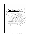
rejecting 160 to 166 MHz by at least 60 dB. The three adjustable coils optimize the
stopband
by providing nulls at the frequencies shown on the schematic. This filter also rejects the LO
frequencies (200 to 300 MHz).
IF
Output
Amplifier
@
The IF output amplifier consists of two common-emitter stages and an output low-pass filter.
The two stages are coupled by Cl4 and L17 which provide high frequency peaking.
AlOA3
1