


A7
A7 M/N Reference, Troubleshooting
Reference
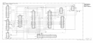
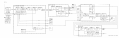
All phase lock loops in the HP 8566B are referenced to the A22 10 MHz Frequency Standard.
The 10 MHz Frequency Standard is used to directly phase-lock the A7A2 100 MHz VCXO
only. All other phase lock loops receive their reference from either the
A7Al
or A7A2 (10 and
20 MHz from the
A7Al
and 100 and 400 MHz from the A7A2).
A malfunction of the 100 MHz VCXO is indicated by all phase lock error messages
(PLl
UNLOCK,PL2UNLOCK,
REFUNLOCK, YTO UNLOCK,
M/NUNLOCK,
and
HETUNLOCK)
being
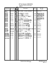
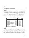
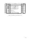
displayed on the HP 8566B CRT. Table 1 lists the phase lock error messages, related
reference, location for measurement, and signal level.
Table 1. Phase Lock Error Messages
Phase Lock Error Message
Reference
output
Level
Frequency
Connector
(dB4
PLl
UNLOCK 100 MHz A7A2J3
0
PLl
UNLOCK 10 MHz
A7AlJ4
0
PL2 UNLOCK 10 MHz
A7AlJ5
0
YTO UNLOCK and M/N UNLOCK 400 MHz
A7A2Jl*
-10
YTO UNLOCK and M/N UNLOCK
20 MIIz
A7AlJ3
0
IIET UNLOCK 100 MHz A7A254
0
All Flags
100 MHz
A7A2J2
0
*
Measure output at end of
A7A2Wl
96 cable.
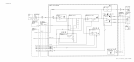
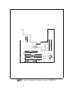
M/N Loop
The M/N Loop consists of a 355 to 395 MHz VCO, part of A7A4, and a phase detector, part
of A7A3. The output of the VCO is divided by two and is used to drive the
AllA
Sampler
assembly. This divided signal is disabled by means of control line LMNE during sweeps when
the frequency span is greater than 5 MHz (fundamental mixing). The two divider numbers, M
and N, are selected by the Al5 Controller such that the Nth harmonic (same as the N divide
number) of the divided VCO output changes in exactly 10 MHz increments as M is changed.
A7 1