


Al5
Al5
Controller,
Circuit
Description
The Al5 controller performs the main control functions of the spectrum analyzer. The
board includes a 16-bit microprocessor (the instrument’s main processor), read-only memory
(ROMs), random-access memory (RAMS), and HP-IB circuitry.
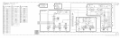
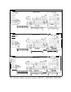
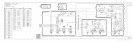
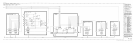
The schematic shows how the main processor, memory, HP-IB, and other circuits on the A15
Controller are interconnected via the microprocessor’s 23-bit address bus and the 16-bit data
bus. To control signal flow on these buses, various signals must be derived from the address
bus signals and the microprocessor’s remaining output signals. These control signals are
generated by two programmable-array-logic integrated circuits (PALS) and other discrete
logic (R/W DECODE, ADDRESS DECODER AND DTACK, ADDRESS DECODE, and
LTIO/LBIO blocks). The signals are used by the microprocessor to control data flow and
address decoding on the Al5 Controller and to control signal flow over the Instrument Bus.
The 16-bit, 8 MHz MC68000 microprocessor receives input through the front panel keyboard
or from HP-IB, performs the necessary decoding and calculations, and outputs the proper
control signals to execute a specific spectrum analyzer operation. Typical main processor
tasks include phase-locking the YTO, selecting the correct sweep time and frequency span,
setting the IF-Display Section resolution bandwidth and sensitivity, and displaying the current
control settings on the CRT through the A3 Digital Storage Section. Instructions that tell the
microprocessor how to accomplish these tasks, the firmware, are stored in ROMs located on
the Al5 Controller. In addition, custom commands and programming can be downloaded into
RAM, permitting specialized operation without requiring a dedicated controller.
The microprocessor performs a brief power-on pretest (POP) at instrument turn-on, verifying
operation of critical circuits and lighting front-panel check LEDs I and II. In addition, LEDs
located on the top edge of the Al5 Controller provide information to help identify particular
faulty circuit components in case a failure occurs.
The instrument’s main memory consists of read-only memory (ROM) and random-access
memory (RAM)
h’
h
w
rc
are located on the Al5 controller. Each 16-bit word in memory is
composed of two 8-bit bytes. The ROM, used to provide permanent storage of the firmware,
is composed of four 32 Kbyte erasable programmable read-only memory (EPROMS). This
provides a total of 64 K-words of ROM. The RAM, used for erasable storage of custom
instructions and programs, is composed of four 8 Kbyte static CMOS memory-integrated
circuits for a total of 16 K-words of RAM. A lithium battery located on the Al5 Controller
provides battery backup power to the CMOS RAM to preserve the contents of memory
when power is removed from the instrument. The typical in-circuit life expectancy of the
non-rechargeable battery is at least three years.
The HP-IB allows the spectrum analyzer to communicate with external devices. It is
implemented using four ICs: a data latch, an HP-IB processor, and two bus transceivers.
The Al5 Controller clock circuit generates an
~-MHZ
clock signal for the 16-bit microprocessor
and a synchronous
~-MHZ
clock signal for the HP-IB processor. The appropriate clock
A15 1