


the output of U3A is high, and CR12 is reverse biased. If the dc input voltage to the
+5.2
V supply is greater than
+8.6
V, then the voltage at pin 5 of
U3B
is greater than
+6.2
V, and the output of
U3B
is high. This turns on transistors Q13 and Q7, pulling
the collector of Q7 to about
+5
V. This provides the HPUP signal.
If any of the above conditions are not met, HPUP remains low. R59 and Cl4 provide an
additional time delay at turn-on to allow the supplies to settle down.
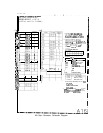
RF
Section
Internal
Fuse
Replacement
Note
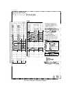
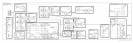
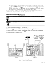
For location of hardware and cables referred to in this procedure, see Figure 1.
3
Warning
Remove ac line cord from both instruments before proceeding with this
9
procedure.
1. Position instrument upside-down as show in view A.
2. Remove feet
@
from rear of RF Section by removing screws
@
show in view A.
3. Remove bottom cover by loosening screw
@
and pulling cover toward rear of instrument.
4. Location of fuses is shown in view B.
Fl
+22V
1A
L
7
,
RE&
I ER
\
Fl
+12V
IA
Fl
-5.2V
2.5A
F2
+ZOV
3A
F2
-40V
1.5A
F3
t5.2V
6A
F3 -lOV 5A
w-
Al7 Al8
POS REG
NEG REG
I
/
VIEW A
Figure 1. Internal Fuse Placement
VIEW B
Al7 3