


A6A8
YTX Replacement
A6A8
YTX Replacement
Note
I
w
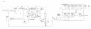
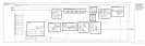
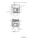
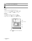
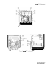
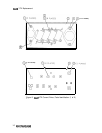
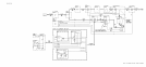
For location of hardware and cables referred to in this procedure, see Figure 4.
Removal
1. Remove ac line cords, separate instrument sections, and remove top and bottom covers
from RF Section.
2. Disconnect cable
@
between All YTO Loop and RF Module.
3. Remove five cables from RF Module PC boards; three from A6A9 Phase Lock and two
from A6A12 YTX Driver.
4. Remove RF Module PC board cover by removing six screws
0.
5. Remove A6A9 assembly and A6A10,
A6Al1,
and A6A12 PC boards.
6. Disconnect 4 (yellow) cable and 5 (green) cable from 2nd Converter to release A6A9
assembly.
7. Remove ribbon cable
@
between A6A7 YTX Current Driver and motherboard.
8. Disconnect 5-pin connector
@
from A6A7 and remove A6A7 by removing two screws
0.
Caution
The A6A8 YTX contains an extremely sensitive diode located inside the
LO/IF connector. This diode is highly susceptible to blow-out from static
discharge. Be very careful when handling the YTX to avoid damaging this
diode.
9. Disconnect all cables from A6A8 YTX.
10. Disconnect bus cable
@
from motherboard.
11. Remove two screws
Q)
holding YTX to motherboard.
12. Remove YTX from RF Module.
Installation
13. Place YTX in RF Module. Be sure insulator is properly installed between YTX and
motherboard.
14. Replace two screws
@)
to attach YTX to motherboard.
15. Reconnect bus cable
@
to motherboard.
Caution
The A6A8 YTX contains an extremely sensitive diode located inside the
LO/IF connector. This diode is highly susceptible to blow-out from static
discharge. Be very careful when connecting cables to the YTX to avoid
damaging this diode. Ground (discharge) all cables before connecting them
the YTX.
A6A7/A6A5/A6A8
7