


Sample and Hold
@
The output of the bandswitch drives preamp U5. U5 and
UlB
together form an op amp with
U5 a low-noise, low-temperature drift preamplifier. U5,
UlB,
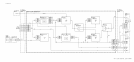
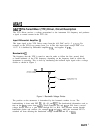
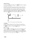
and U6 are used in a sample and
hold circuit as shown in Figure 2.
Q15, a JFET, is used as the switch for the sample and hold. The switch is opened (that is,
the FET is turned off) whenever a bandcrossing occurs. When a bandcrossing occurs, the
input voltage at
Jl
changes as the YTO Loop resets its frequency to start a new band, and
the YTX bandswitch changes bands. At this time, the voltage at the input of U5 varies.
The sample and hold circuit is used to prevent these variations from reaching the YTX.
The sample and hold switch is controlled through Q14 by a signal from the
A6All
Slope
Generator. R44, R45, CRlO, and CR11 keep the output of
UlB
from saturating when the
feedback loop is opened by Q15 being off. This prevents a “glitch” at the output of U6 when
the loop closes if
UlB
suddenly had to recover from a saturated condition.
FROM
BANDSWITCH
R48
1K
TP5
i
20K
TO
IF
OFFSET
Figure 2. YTX Driver Sample and Hold, Simplified Schematic
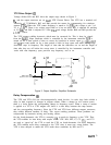
IF Offsets
@
In addition to tracking a harmonic of the YTO, the YTX must be offset from this LO
harmonic by the first IF (321.4 MHz). This is done by U7A and its associated components.
Q7 to
QlO
switch in different IF offset adjustments for each band. The YTX peaking signal
from
A6All
Slope Generator is also summed into U7A through R77.
Sweep + Tune
@I
Since the U5,
UlB,
and U6 combination have a gain of 1.05 set by R48 and R75, the voltage
at TP5 has an sensitivity of -0.525
V/GHz
(YTX). Th
is
signal goes to the
A6All
Slope
Generator, to voltage divider R54 and R55, and to U8. U8 is set to give -1
V/GHz
at its
output which goes to J2. This signal is cabled to the rear panel of the instrument to provide
an analog voltage proportional to input frequency. U2A and its associated circuitry provide an
offset voltage for U8 to correct for the first IF (3.6214 GHz) in the 0 to 2.5 GHz band. R98 is
adjusted for 0 V at U2 with the spectrum analyzer tuned to 0 Hz.
2
A6A12