


A5
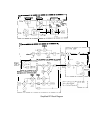
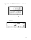
A5 Front Panel, Circuit Description
The A5 Front Panel comprises the
A5Al
Keyboard, A5A2 Rotary Pulse Generator (RPG),
Instrument Check indicator
LEDs,
LINE power switch, STANDBY power indicator LED, and
CAL OUTPUT connector and cable. The RF INPUT, 1ST LO OUTPUT, and 321.4 MHz
IF INPUT and IF OUTPUT connectors are physically part of the A6 RF Module and are
described in detail in that section.
A5Al
Keyboard
A5Al
Keyboard includes the 49 pushbutton switches and 9 associated indicator
LEDs
on the
RF Section front panel.
Keyboard Switches
@
Each of the normally open SPST switches consists of a spring-loaded contact and a pair
of printed-circuit board contacts. All but two of the keyboard switches are organized in a
matrix of rows and columns. When a front-panel key is pressed, the corresponding SPST
switch is closed, connecting a normally grounded key row to a key column. The grounded
key column signal is detected on the Al2 Front Panel Interface,
signalling
the Al5 Controller
to immediately halt the sweep. Then, the Al5 Controller polls (grounds) each of the key
rows sequentially (starting with key row 0) to identify the particular front panel key that is
pressed. During normal operation, the front-panel SWEEP LED can be observed to blink off
momentarily as the Al5 Controller halts the sweep, polls both the IF Section keyboard and
the RF Section keyboard, and then reacquires phaselock before continuing on with the sweep.
Indicator
LEDs
@
The nine keyboard indicator LEDs and the two INSTR CHECK indicator LEDs are lighted
selectively by the Al5 Controller to indicate the state of coupled functions, SIGNAL TRACK
(on/off), DATA entry (
enabled/disabled), HP-IB control status (remote and addressed), and
self-test. U2 and U3 latch the LED data from the Data Bus. All front-panel LEDs are lighted
momentarily during the turn-on self test for verification.
The two INSTR CHECK indicator LEDs are lighted selectively by the Al5 Controller to
indicate the overall results of the most recent instrument self test. An instrument self test is
performed each time the LINE switch is switched to ON or the
(INSTR
PRESET] key is pressed.
Both
LEDs
are lighted at the start of each self test, and both are turned off upon successful
test completion; if one or both of the INSTR CHECK LEDs remain on, an instrument fault
has been detected. Refer to the Al5 Controller section for detailed information about the self
test.
A5 1