


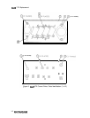

300 MHz Power Amplifier
@I
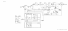
The output of the 300 MHz Power Amplifier, approximately
+20
dbm, is the local oscillator
for the A6A3 Last Converter. Capacitor
C30
reduces the sub-harmonic content of the output.
The output filter C52, L21, and C53, reduces higher order harmonics while maintaining a
500
output impedance.
Sampler Driver
@I
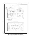
Amplifier U2 drives the Sampler step-recovery diode (function block E) with the 100
MHz signal at a level of approximately
+20
dBm.
Capacitors C8, C9, and L4 match the
forward-biased impedance of the diode to U2. Resistor R5 loads the output of U2 during the
diode’s reverse biased condition.
Sampler
@
and Loop Integrator
@
The output of the sampler is a dc voltage proportional to the phase difference between the
33rd harmonic of the 100 MHz reference and the 3.3 GHz second local oscillator (A6A4
Second Converter). Integrator U3 supplies a tune voltage to the 3.3 GHz second local
oscillator. This heterodyne loop phase locks the oscillator to the 100 MHz reference signal.
Potentiometer R38 adjusts the output balance of the sampler. Capacitor C46 is the integrator
capacitor for U3.
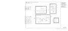
Aided Acquisition and Unlock Detector
@
The output tune voltage from the Loop Integrator (function block F) becomes
-
25 V when
the 3.3 GHz Heterodyne Loop is unlocked. The Aided Acquisition circuitry detects this
condition and retunes the 3.3 GHZ oscillator on the A6A4 Second Converter assembly within
the capture range of the phase-lock loop. The Aided Acquisition circuitry also controls the
Lock Indicator (function block J).
The Negative Rail Detector U4A is an inverting comparator.
The threshold voltage at pin 5 is
set at -23.5 V. During unlock, the input of U4A becomes more negative than the threshold
voltage and the comparator output becomes positive. Resistor R21 provides positive feedback,
stabilizing the circuit. Resistors R25 and R26 form a voltage divider reducing the input to
U4B
below the value of the power supplies. The positive output of U4A triggers One Shot
multivibrator U4B. The negative output of U4B forward biases diodes CR1 and CR2. The
diodes become a constant current source for integrator capacitor C46 (function block F),
causing a positive direction search ramp of voltage at the output of U3. This search ramp
tunes the 3.3 GHz second local oscillator through the capture range of the phase-lock loop.
If the phase-lock loop does not phase-lock on the search ramp, the tune voltage will remain
positive until the One Shot recovers, reverse biasing CR1 and CR2. The output of U3 then
becomes negative (unlock condition), causing the Aided Acquisition circuitry to repeat the
search cycle until phase-lock occurs. This results in a sawtooth tune waveform with a period
of approximately 6 ms.
The One Shot pulse width of approximately 1 ms is controlled by R24 and C38. This is the
time it takes for the voltage on pin 7 to decay to -25 V to less the -20 V. During this time,
the input to U4C has become -20 V due to the positive tune voltage ramp. In high band the
3.3 GHz second local oscillator is switched
off;
the PIN signal goes negative, which disables
the search ramp and unlock detector through CR3.
2
A6A9