


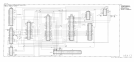

Integrating Amplifier
@
Q4 is a differential input pair which together with
Q5
and Q6 forms a high gain amplifier.
Feedback is added with C32 and R49 to make an integrating amplifier. C32 provides ac
feedback only, so for the amplifier to remain linear, dc feedback is accomplished by virtue of
the entire phase-lock loop.
VCXO Divider and Buffers
@
100 MHz from the A7A2 VXCO is applied to the counter U3 which divides by 5, then by
2. Its outputs are 10 MHz and 20 MHz which are buffered by U4 to be used as reference
frequencies by other assemblies in the instrument. The other 10 MHz output is used to drive
the Phase Lock Sampler
@J
and Lock Indicator Sampler
0.
45”
Phase Lead and Buffer Amplifier
@
and
45”
Phase Lag and Buffer Amplifier
@
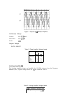
The 45’ phase shift buffers are used to provide two 10 MHz signals which are 90” apart in
phase, the purpose of which is explained in Lock Indicator Sampler description. 45” phase
shift in
@
is accomplished with C35 and R53, while in
@)
it is done by R59 and C38.
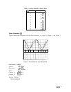
Lock Indicator Sampler
(ij
The lock indicator sampler functions the same as the phase lock sampler
0.
The only
difference is that the 10 MHz is 90” shifted in phase. This causes the output of the lock
indicator sampler to be maximum negative voltage when the loop is locked, since in this state
the output of the phase-lock sampler is 0 V.
Phase Lock Detector
@
The output of the lock indicator sampler is compared to -0.5 V by U5. When the output
voltage becomes closer to 0 than to -0.5 V, U5 switches its output to TTL high to indicate to
the Al5 Controller that the 100 mHz Reference phase-lock loop is unlocked.
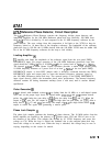
During instrument warmup, the A22A2 10 MHz Quartz Crystal Oscillator remains off for a
few minutes until thermal equilibrium is reached. It is normal for both an OVEN COLD and
REF UNLOCK indication to appear on the CRT during these first few minutes of instrument
operation after a cold start.
2
A7A1