


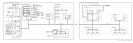
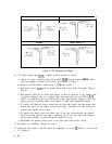

LED LEAD IDENTIFICATION INSTR CHECK I
..,I-:;;:;
*g;;;
~iz::~
STANDBY INSTR CHECK II
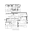
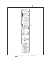
Figure 2. LED Removal and Repair
11. To replace signal input
LEDs,
switches, or keys, proceed as follows.
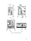
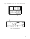
a. Loosen set screw in DATA control knob (RPG) @@ using a number 4
allen
wrench
(HP part number 8710-0857) and remove knob. Refer to Figure 3.
b. Remove nut from DATA control using a
7/16
inch wrench.
c. Remove 14 screws @@ and lift printed circuit board away from front panel. Refer to
Figure 3.
d. Pull defective LED out of socket with fingers (it may be necessary to pry slightly with
a pointed instrument such as a soldering aid), trim both leads on new LED to 3/B
inch (1 cm) and insert the new LED in the socket with negative (cathode) lead to the
square pad on the printed circuit board. Refer to LED lead identification below.
e. To remove the defective switch, remove the key from the switch, melt the plastic pins
holding the switch to the printed circuit board using a soldering iron, and remove the
switch from printed circuit board.
f. To replace the switch, insert the plastic pins of the new switch through the printed
circuit board and melt the pins with a soldering iron on the rear side of the printed
circuit board enough to secure the switch. Replace the key.
g. Reassemble the printed circuit board to the front panel and connect cables.
12. Reconnect the connectors removed in step 9.
13. Secure the front panel to the RF section by tightening six screws
0.
Refer to views B and
C of Figure 1.
1
4 A5