


4 - 61
4 POSITIONING SIGNALS
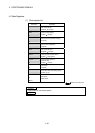
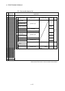
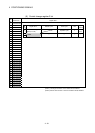
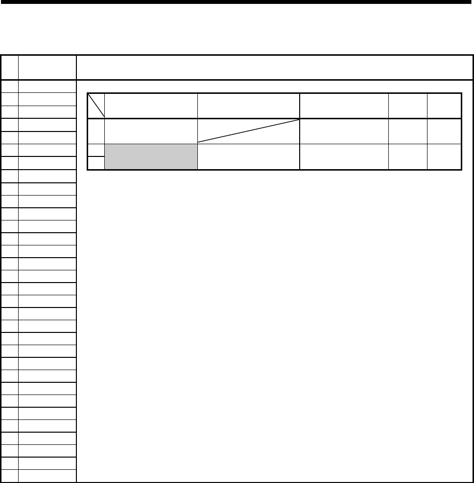
(6) Control change register 2 list
Axis
No.
Device No. Signal name
1
D1536 to D1538
2
D1539 to D1541
3
D1542 to D1544
Signal name Refresh cycle Fetch cycle Unit
Signal
direction
4
D1545 to D1547
5
D1548 to D1550
0
Override ratio setting
register (0 to 100)
Operation cycle
%
Command
device
6
D1551 to D1553
1
7
D1554 to D1556
2
Unusable — — — —
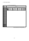
8
D1557 to D1559
9
D1560 to D1562
10
D1563 to D1565
11
D1566 to D1568
12
D1569 to D1571
13
D1572 to D1574
14
D1575 to D1577
15
D1578 to D1580
16
D1581 to D1583
17
D1584 to D1586
18
D1587 to D1589
19
D1590 to D1592
20
D1593 to D1595
21
D1596 to D1598
22
D1599 to D1601
23
D1602 to D1604
24
D1605 to D1607
25
D1608 to D1610
26
D1611 to D1613
27
D1614 to D1616
28
D1617 to D1619
29
D1620 to D1622
30
D1623 to D1625
31
D1626 to D1628
32
D1629 to D1631
(Note-1): The range of axis No.1 to 8 is valid in the Q172HCPU.
(Note-2): Device area of 9 axes or more is unusable in the Q172HCPU.