


4 - 10
4 POSITIONING SIGNALS
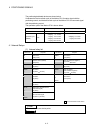
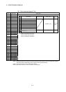
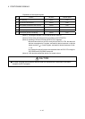
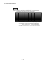
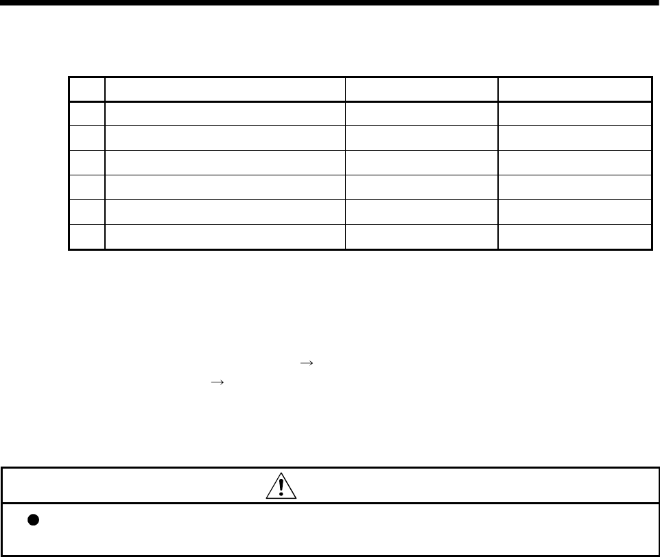
Explanation of the request register
No. Function Bit device Request register
1 PLC ready flag M2000 D704
2 All axes servo ON command M2042 D706
3 JOG operation simultaneous start command M2048 D708
4 Manual pulse generator 1 enable flag M2051 D755
5 Manual pulse generator 2 enable flag M2052 D756
6 Manual pulse generator 3 enable flag M2053 D757
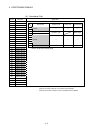
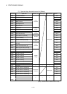
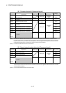
(Note-1): The range of axis No.1 to 8 is valid in the Q172HCPU.
(Note-2): Device area of 9 axes or more is unusable in the Q172HCPU.
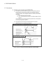
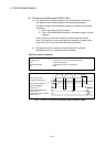
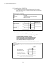
(Note-3): Handling of D704 to D708 and D755 to D757 registers
Because cannot be turn on/off for every bit from the PLC CPU, the above bit
devices are assigned to D register, and each bit device becomes on with the
lowest rank bit 0
1 of each register, and each bit device becomes off with
1
0.
Use it when the above functions are requested from the PLC CPU using the
S(P).DDRD and S(P).DDWR instruction.
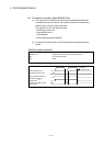
(Note-4): It can also be ordered the device of a remark column.
CAUTION
The data executed later becomes effective when the same device is executed in the Motion
program and PLC program.