


3 - 26
3 MOTION DEDICATED PLC INSTRUCTION
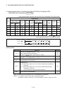
[Setting range]
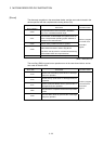
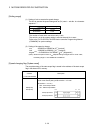
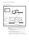
(1) Setting of axis to execute the speed change.
The axis to execute the speed change set as (S1) sets J + axis No. in a character
sequence " ".
(S1) usable range
Q173HCPU 1 to 32
Q172HCPU 1 to 8
The number of axes which can set are only 1 axis.
The axis No. set in the system setting is used as the axis No. to start.
Refer to the "Q173HCPU/Q172HCPU Motion controller Programming Manual
(COMMON)" for system settings.
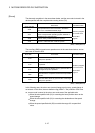
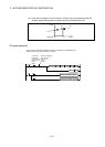
(2) Setting of the speed to change.
mm : -6000000 to 6000000
10
-2
[mm/min]
inch : -6000000 to 6000000
10
-3
[inch/min]
degree
(Note)
: -2147483648 to 2147483647 10
-3
[degree/min]
(Note) : When the "speed control 10 multiplier setting for degree axis" is set to "valid",
the setting range is "-2147483648 to 2147483647".
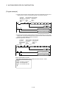
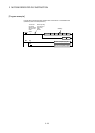
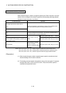
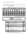
[Speed changing flag (System area)]
The complete status of the start accept flag is stored in the address of the start accept
flag in the shared CPU memory.
Shared CPU memory
address
( ) is decimal address
Description
206H(518)
207H(519)
The start accept flag is stored by the 1 to 32 axis, each bit.
(As for a bit's actually being set Q173HCPU : J1 to J32/
Q172HCPU : J1 to J8.)
OFF : Start accept usable
ON : Start accept disable
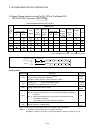
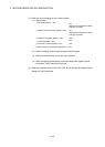
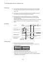
206H(518) address
207H(519) address
J2
J1
b1 b0b15
J16
J32
J17