


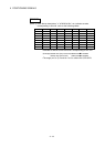

4 - 18
4 POSITIONING SIGNALS
POINTS
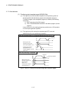
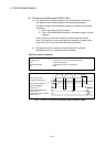
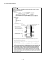
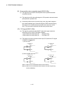
Example 1, 2 are shown below about in-position signal and command in-position
signal of the interpolation axis.
[Example1]
G0 travel block
Start accept flag (M2001+n)
In-position signal (M2402+20n)
X
Y
Z
Command in-position range
In-position range
Motion program (Axis
designation program) start
Command in-position signal
(M2403+20n)
X
Y
Z
Axis X,Y speed
(Z-axis does not travel)
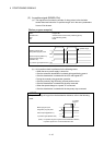
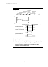
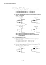
PLC program
Start
command
To self CPU
high sped
interrupt accept
flag from CPU
U3E1\G48.0
Start accept flag
of the axis No.1
(CPU No.2)
U3E1\G516.0
Start accept flag
of the axis No.2
(CPU No.2)
U3D1\G516.1
Start accept flag
of the axis No.3
(CPU No.2)
U3E1\G516.2
Motion program
O100;
G91;
G00 X100. Y100.;
M02;
%
Operation timing
SP.SVST H3E1 "J1J2J3" K100 D0
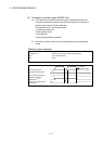
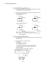
(1) The in-position signal turns ON by reaching the in-position range of servo
parameter after deceleration start.
Since the Z-axis is stopped in this case, it always turns on immediately after
deceleration start.
Even if the only 2 axes (X,Y) is commanded in the G00 command of Motion
program, when the 3 axes is started by SVST instruction in the PLC program,
the in-position signal turns ON after deceleration start in the Z-axis as X,Y-axis.
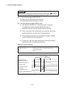
(2) The command in-position signal turns ON when the difference between the
command position of Motion program and the absolute position of machine
value is less than the command in-position range set in the fixed parameter.
Since the command of Z-axis is not described in this program, the command in-
position check is not executed during travel of Z-axis and it remains OFF from
start to stop of travel.