


6 - 59
6 MOTION PROGRAMS FOR POSITIONING CONTROL
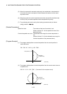
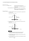
6.13.4 G03 Circular interpolation CCW (Central coordinates-specified)
Code G03
Function
Circular interpolation (CCW)
Circular arc central
coordinates-specified
The axes travel from the current position (start point) to the specified
coordinate position (end point) with a circular arc (CCW).
The travel speed is the specified feed rate.
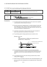
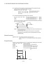
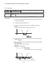
Format
0
Feed rate
Feed rate command
3XxGYyIiJj
Circular arc center coordinates 1, 2
End point X, Y coordinates
;Ff
[Explanation]
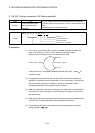
(1) The incremental values (always use incremental values) from the current position
(start point) is used to command the circular arc center coordinates.
For G03 (CCW), give the end point coordinates of the circular arc with the address
(must be specified for 2 axes) and specify the central coordinates of circular arc
with I and J.
The central coordinates 1, 2 are I and J in order of lower axis No.s.
When X=Axis 1, Y=Axis 2, I=1(X), J=2(Y)
When X=Axis 2, Y=Axis 1, I=1(Y), J=2(X)
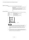
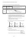
(2) Always specify the end point coordinates for 2 axes as they cannot be omitted.
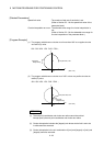
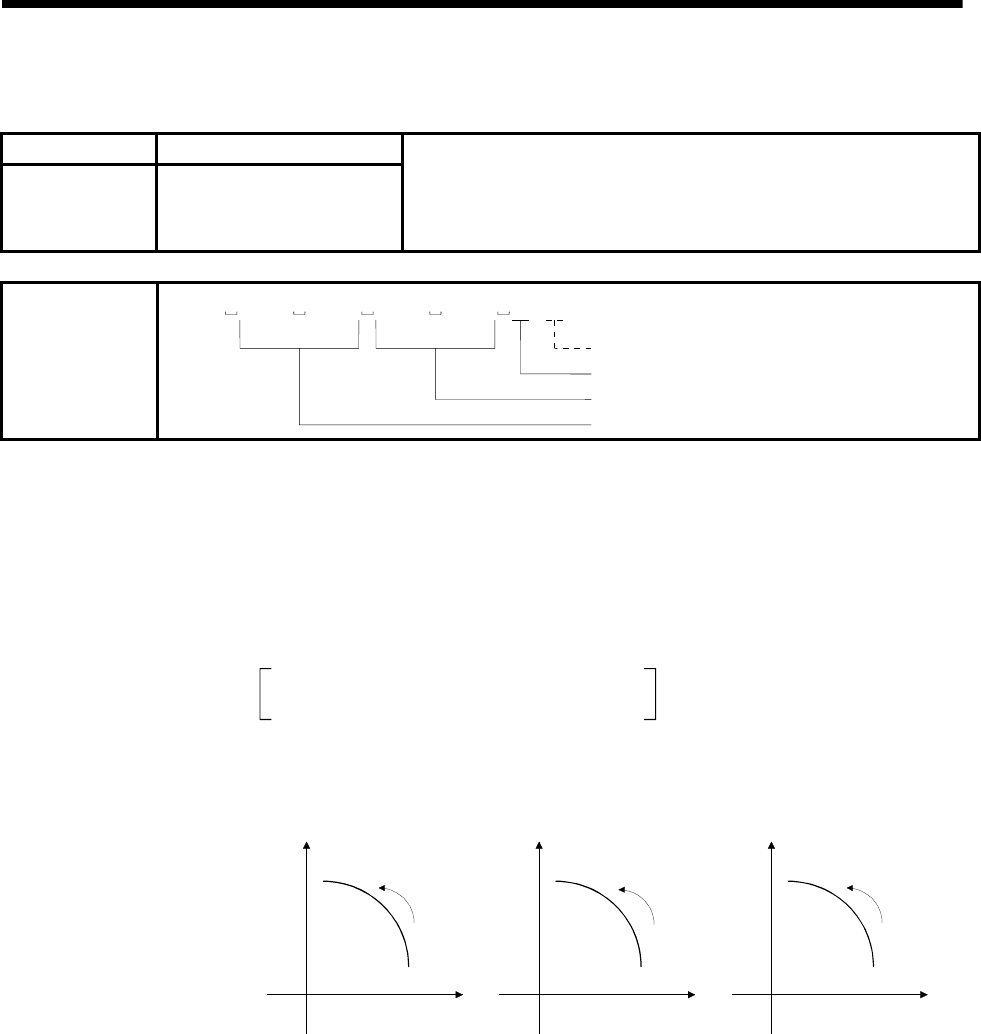
G03 (CCW) : Counterclockwise
Y
X
G03
X
Z
Z
Y
G03 G03
X-axis=Lower axis Z-axis=Lower axis Y-axis=Lower axis
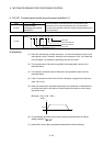
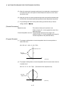
(3) If the end point is in the same position as the start point, the circular arc is 360°
(complete round).
(4) If they cannot be linked by a circular arc,
Within the allowable error range for circular interpolation : The start and end
points are
connected by helical
interpolation.
Beyond the allowable error range for circular interpolation : An error occurs at the
circular arc start point.