


5 - 20
5 PARAMETERS FOR POSITIONING CONTROL
5.4 Work Coordinate Data
(1) The work coordinate data is used to set the work coordinates and six different
work coordinates can be set (G54 to G59) for every axis. (Refer to Section 6.12 for
details.)
(2) The position is set with the offset from the mechanical coordinate system home
position for the work coordinate system. The offset setting value is the distance
from the mechanical coordinate system home position (0).
(3) The work coordinate data is set using the peripheral devices.
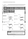
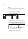
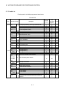
(4) The work coordinate data to be set are shown in Table 5.3.
Table 5.3 Work Coordinate Data List
Setting range
mm inch degree
No. Item
Setting range Units Setting range Units Setting range Units
Initial
value
Units Remarks Section
1 G54
2 G55
3 G56
4 G57
5 G58
6 G59
-214748.3648
to
214748.3647
mm
-21474.83648
to
21474.83647
inch
-359.99999
to
359.99999
degree 0 mm
Set the work coordinate system 1 to 6.
6.12
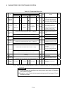
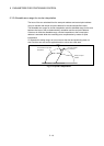
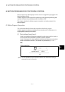
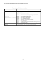
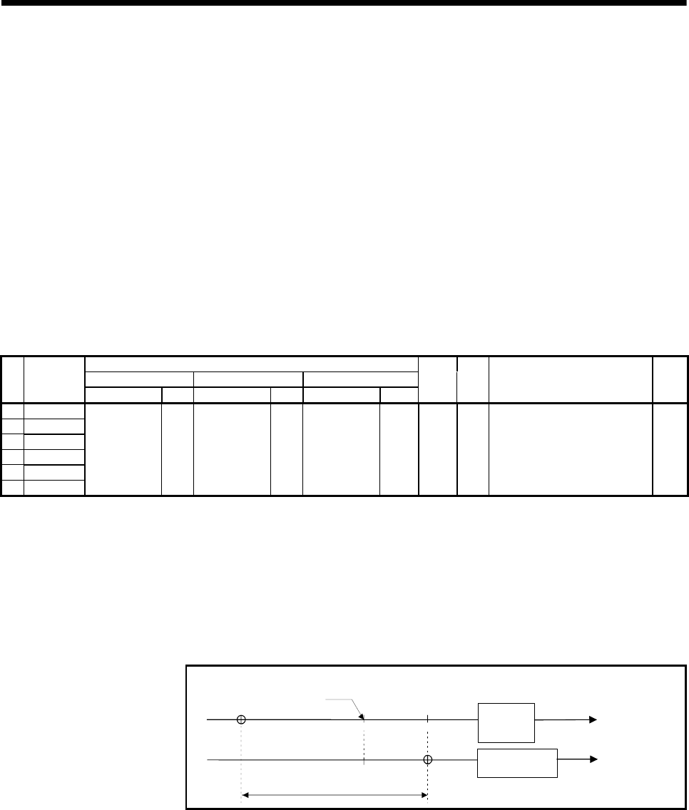
(5) When a home position return is made based on the home position return setting
data, the mechanical coordinate system and work coordinate system are as
shown below.
[Example] The X-axis home position address of home position return data is set
to 200.00[mm] and the X-axis: G54 of the work coordinate data is set
to 300.00[mm] to make a home position return.
-
Home position return
complete point
200.00
+
Mechanical
coordinate
system
-
300.00
-100.00
G54=300.00 [mm]
+
0
Work coordinate
system (G54)
Monitor data
machine value
Current value
0
On completion of a home position return, the machine value is equal to
200.00[mm] and the current value is equal to -100.00[mm].
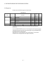
When the work coordinate data is set to 0, the current value is equal to the
machine value.