


5 - 2
5 PARAMETERS FOR POSITIONING CONTROL
5.2 Fixed Parameters
(1) The fixed parameters are set for each axis and their data is fixed based on the
mechanical system, etc.
(2) The fixed parameters are set using a peripheral device.
(3) The fixed parameters to be set are shown in Table 5.1.
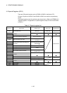
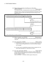
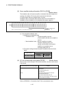
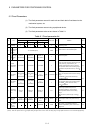
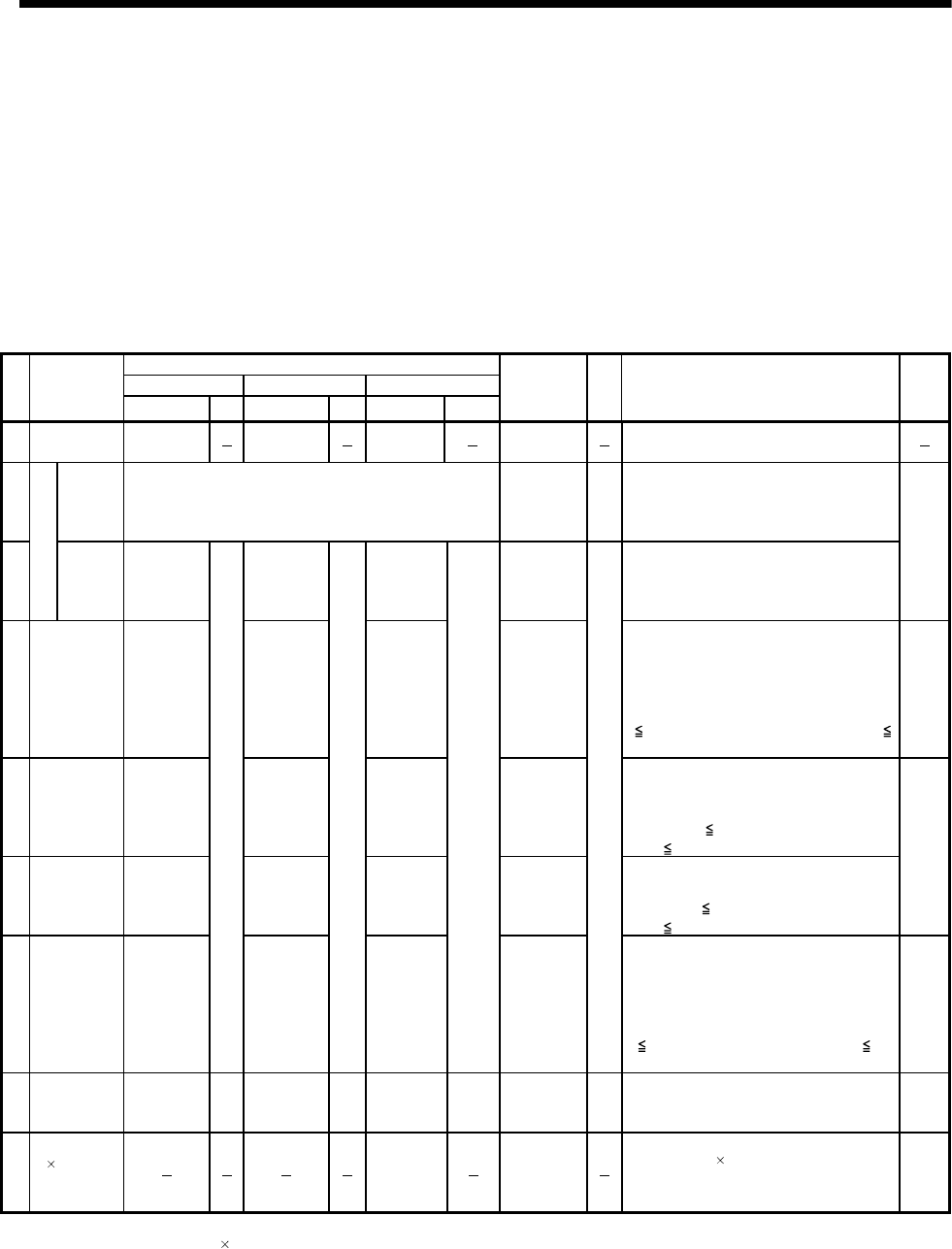
Table 5.1 Fixed parameter list
Setting range
mm inch degree
No. Item
Setting range Units Setting range Units Setting range Units
Initial value Units Remarks Section
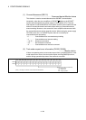
1 Unit setting 0
1
2
0
• Set the command value for each axis at the
positioning control.
2
Number of
pulses per
rotation
(AP)
1 to 2147483647[PLS] 20000 PLS
• Set the number of feedback pulses per motor
rotation based on the mechanical system.
3
Travel value per pulse (A)
Travel
value per
rotation
(AL)
0.0001 to
214748.3647
0.00001 to
21474.83647
0.00001 to
21474.83647
2
• Set the travel value per motor based on the
mechanical system.
5.2.1
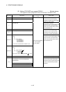
4
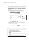
Backlash
compensation
amount
(Note-1)
0 to 6.5535 0 to 0.65535 0 to 0.65535 0
• Set the backlash amount of the machine.
• Every time of the positioning direction changes
at the positioning, compensation by the
backlash compensation amount is executed.
The expression below shows the setting range.
0
(backlash compensation amount) × AP/AL
65535
5.2.2
5
Upper stroke
limit
(Note-1)
-214748.3648
to
214748.3647
-21474.83648
to
21474.83647
0 to
359.99999
214748.3647
• Set the upper limit for the machine travel
range. The expression below shows the setting
range.
-2147483648
(upper stroke limit value) ×
AP/AL
2147483647
6
Lower stroke
limit
(Note-1)
-214748.3648
to
214748.3647
-21474.83648
to
21474.83647
0 to
359.99999
0
• Set the lower limit for the machine travel range.
The expression below shows the setting range.
-2147483648
(lower stroke limit value) ×
AP/AL
2147483647
5.2.3
7
Command in-
position range
(Note-1)
0.0001 to
3.2767
mm
0.00001 to
0.32767
inch
0.00001 to
0.32767
degree
0.01
mm
• Set the position at which the command in-
position signal (M2403+20n) turns on
[(positioning address) - (current value)].
The expression below shows the setting
range.
1
(command in-position range) × AP/AL
32767
5.2.4
8
High-speed
feed rate
0.01 to
6000000.00
mm/
min
0.001 to
600000.00
inch/
min
0.01 to
2147483.647
(Note-2)
degree/
min
2000.00
mm/
min
• Set the positioning speed by G00.
• Set the speed at the home position return by
G28.
5.2.5
9
Speed control
10
multiplier
setting for
degree axis
Invalid/Valid
Invalid
• Set whether the positioning control is executed
with a value 10
multiplier the speed of a
command speed setting, when a control unit is
degree axis.
5.2.6
(Note-1) : The display of the possible setting range changes according to the electronic gear value.
(Note-2) : When the "speed control 10 multiplier setting for degree axis" is set to "valid", the setting range for high-speed feed rate is 0.01 to 21474836.47[degree/min].