


4 - 1
4 POSITIONING SIGNALS
4. POSITIONING SIGNALS
The internal signals of the Motion CPU and the external signals to the Motion CPU
are used as positioning signals.
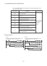
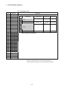
(1) Internal signals
The following five devices of the Motion CPU are used as the internal signals of
the Motion CPU.
• Internal relay (M) .............................. M2000 to M3839 (1840 points)
M4000 to M4719 (720 points)
• Special relay (SP.M) ........................ M9073 to M9079 (7 points)
• Data register (D) .............................. D0 to D1631 (1632 points)
D1650 to D1679 (30 points)
• Motion register (#) ........................... #8000 to #8191 (192 points)
• Special register (SP.D) .................... D9112 and D9180 to D9201 (23 points)
(2) External signals
The external input signals to the Motion CPU are shown below.
• Upper/lower limit switch input .......... The upper/lower limit of the positioning
range is controlled.
• Stop signal ....................................... Stop signal for speed control
• Proximity dog signal ........................ ON/OFF signal from the proximity dog
• Manual pulse generator input .......... Signal from the manual pulse generator
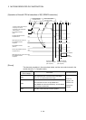
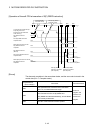
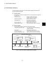
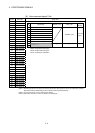
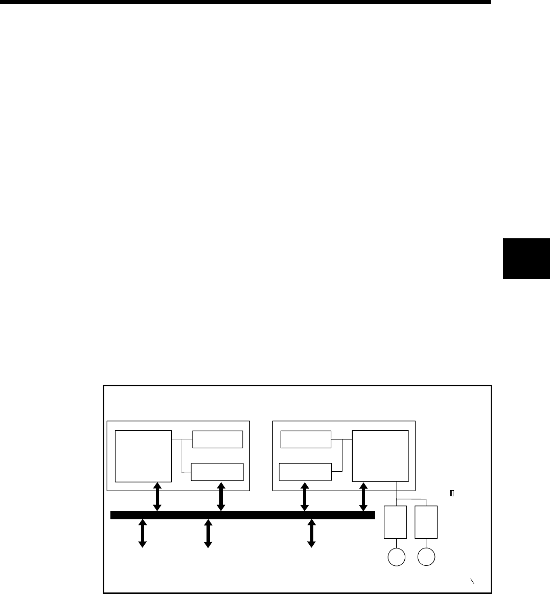
Configuration between modules
Sensor, solenoid, etc.
(DI/O)
Motion CPU
Shared CPU
memory
1)
PLC CPU
Device memory
PLC control
processor
Motion control dedicated I/F
(DOG signal, manual
pulse generator)
Device memory
2)
M
M
SSCNET
Servo amplifier
Servomotor
PLC bus
Note) : Device memory data : 1) = 2)
Shared CPU
memory
Motion control
processor
PLC intelligent function
module (A/D, D/A, etc.)
Fig.4.1 Flow of the internal signals/external signals
4