


7 - 68
7 AUXILIARY AND APPLIED FUNCTIONS
7.7 Override Ratio Setting Function
The speed change can be executed by setting the override ratio to the command
speed of the Motion program in this function.
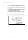
[Control details]
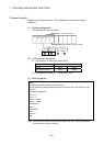
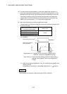
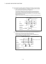
(1) The override ratio is set in the range of 0 to 100[%] in 1[%] units to the command
speed in the Motion program. The value obtained by multiplying the command
speed by the override value is the real feed speed.
(2) The override ratio is set to each axis.
The default value is 100[%] in all axes.
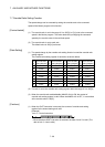
[Data Setting]
(1) The speed change by the override ratio setting function is used the override ratio
setting register.
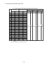
The override ratio setting register of each axis are shown below.
A
xis
No.
Override Ratio
Setting Register
A
xis
No.
Override Ratio
Setting Register
A
xis
No.
Override Ratio
Setting Register
A
xis
No.
Override Ratio
Setting Register
1 D1536 9 D1560 17 D1584 25 D1608
2 D1539 10 D1563 18 D1587 26 D1611
3 D1542 11 D1566 19 D1590 27 D1614
4 D1545 12 D1569 20 D1593 28 D1617
5 D1548 13 D1572 21 D1596 29 D1620
6 D1551 14 D1575 22 D1599 30 D1623
7 D1554 15 D1578 23 D1602 31 D1626
8 D1557 16 D1581 24 D1605 32 D1629
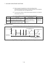
(2) The ratio is set to the override ratio setting register within the range of 0 to 100[%].
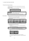
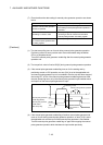
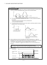
(3) When the override ratio enable/disable (M4405+10n) is ON, the content of
override ratio setting register is valid. When the M4405+10n is OFF, it is controlled
at the override ratio of 100[%].
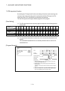
[Cautions]
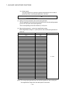
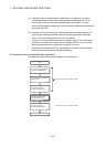
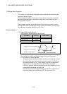
(1) When the SVST instruction is executed, the content of override ratio setting
register for the lowest starting axis valid.
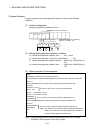
[Example]
Axis 2, 3, 4 start instruction
SP.SVST
K100 M0 D0
H3E3
"J2J3J44"
• When the above SVST instruction is executed, the data of axis 2 is valid. (The
data of axis 3, 4 are invalid.)