


6 - 70
6 MOTION PROGRAMS FOR POSITIONING CONTROL
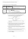
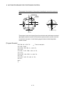
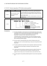
6.13.9 G12 Helical interpolation CW (Helical central coordinates-specified)
Code G12
Function
Helical interpolation (CW)
Helical central coordinates-
specified
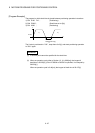
The linear interpolation to other linear axis is executed performing 2
axes circular interpolation from the current position (start point) to
circular end address or linear axis end point address, and the helical
interpolation (CW) is executed so that it may become a spiral course.
The travel speed is the specified combined-speed for 2 axes circular
interpolation axis.
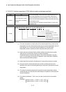
Format
1
Feed rate
Feed rate command
2XxGYyZz
Number of pitches (0 to 999)
Pitch command
;FfIiJjPp
Circular arc central coordinates 1, 2
(Relative address)
Linear axis end point Z coordinates
Circular interpolation axis end point
X, Y coordinates
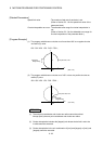
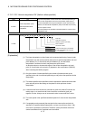
[Explanation]
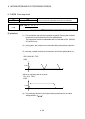
(1) The linear interpolation to other linear axis is executed performing 2 axes circular
interpolation from the current value (start point) to circular interpolation axis end
point address (X,Y) or linear axis end point address (Z), and the helical
interpolation is executed so that it may become a spiral course.
(2) Always use the incremental values (relative address) from the current position
(start point) to command the circular arc central coordinates.
An absolute values or incremental values of the circular interpolation axis end
point (X,Y) and linear axis end point (Z) depends in the modal status (G90/G91)
when executing the Motion program.
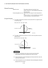
(3) Always specify the end point coordinates for 3 axes as they cannot be omitted.
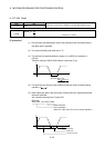
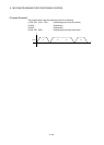
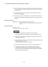
(4) Only the number of times specified by the number of pitches around on the
specified circle, and it is executed positioning to end point at the specified circular
interpolation.
(5) The center coordinates-specified circle specifies circular interpolation method
connected start point and end point at the seeing on the plane for which performs
circular interpolation.
(6) The central coordinates 1, 2 are I and J in order of lower axis No.s by system
setting.
[Example]
When X=Axis 1, Y=Axis 2, I=1(X), J=2(Y)
When X=Axis 2, Y=Axis 1, I=1(Y), J=2(X)