


3 - 7
3 MOTION DEDICATED PLC INSTRUCTION
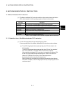
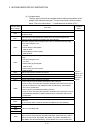
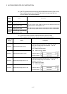
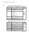
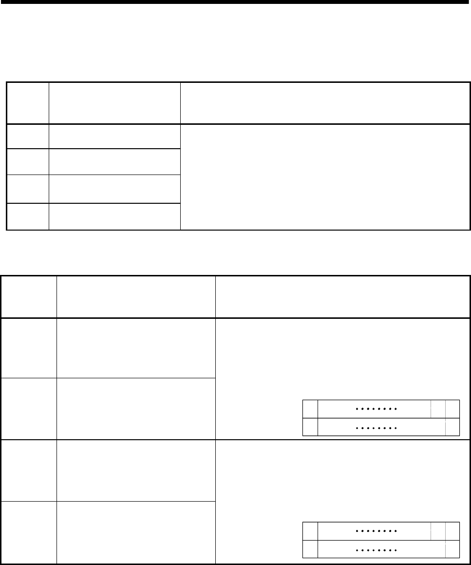
(4) Self CPU operation data area used by Motion dedicated instruction (30H to 33H)
The complete status of the to self CPU high speed interrupt accept flag from
CPUn is stored in the following address.
Shared
CPU
memory
address
Name Description
30H(48)
To self CPU high speed interrupt
accept flag from CPU1
31H(49)
To self CPU high speed interrupt
accept flag from CPU2
32H(50)
To self CPU high speed interrupt
accept flag from CPU3
33H(51)
To self CPU high speed interrupt
accept flag from CPU4
This area is used to check whether to self CPU high speed interrupt accept
flag from CPUn can be accepted or not.
0: To self CPU high speed interrupt accept flag from CPUn accept usable.
1: To self CPU high speed interrupt accept flag from CPUn accept disable.
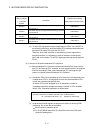
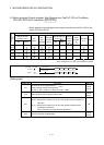
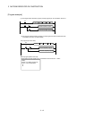
(5) System area used by Motion dedicated instruction (204H to 20DH)
The complete status of the each flag is stored in the following address.
Shared CPU
memory
address
Name Description
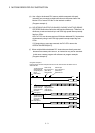
204H(516) Start accept flag (Axis1 to 16)
205H(517) Start accept flag (Axis17 to 32)
The start accept flag is stored by the 1 to 32 axis, each bit.
(As for a bit's actually being set Q173HCPU : J1 to J32/
Q172HCPU : J1 to J8.)
OFF : Start accept flag usable
ON : Start accept flag disable
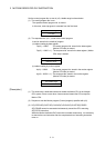
204H(516) address
205H(517) address
J2
J1
b1 b0b15
J16
J32
J17
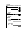
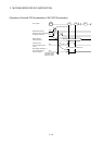
206H(518) Speed changing flag (Axis1 to 16)
207H(519) Speed changing flag (Axis17 to 32)
The speed changing flag is stored by the 1 to 32 axis, each bit.
(As for a bit's actually being set Q173HCPU : J1 to J32/
Q172HCPU : J1 to J8.)
OFF : Start accept usable
ON : Start accept disable
206H(518) address
207H(519) address
J2
J1
b1 b0b15
J16
J32
J17