


E6581301
E-37
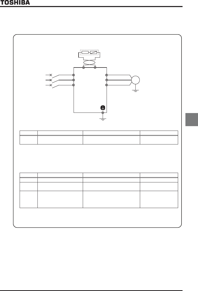
5
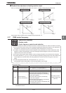
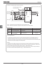
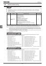
All 200V VF-AS1 and 400V VF-AS1 with ratings of up to 160kW have built-in dynamic braking transistors as
standard equipment. If the rating of your inverter falls within this range, connect the resistor, as shown in
Figure a) below or Figure b) on the next page. If your inverter has a power rating of 200kW or more, connect
a resistor, as shown in Figure c).
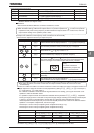
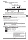
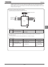
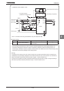
Connecting an external braking resistor (optional)
a) External braking resistor (with a thermal fuse) (optional)
IM
Motor
R/L1
S/L2
T/L3
Three-phase
main circuit
Power supply
PA/+
PB
MCCB
An external braking resistor
(optional)
PBR
Inverter
U/T1
V/T2
W/T3
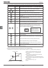
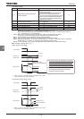
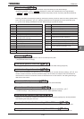
[Parameter setting]
Title Function Adjustment range Setting value
RD Dynamic braking selection
:Disabled
~:Enabled
ŬDo not connect an external resistor with a resistance (combined resistance) smaller than the minimum
admissible resistance.
For overload protection, be sure to set the parameters RDT and RDER properly.
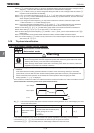
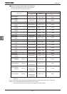
[Parameter setting]
Title Function Adjustment range Setting value
RDT Dynamic braking resistance ~ Any value
RDER
Dynamic braking resistor
continuous capacity
~ kW Any value
H
Braking resistance overload
time
~ sec.
Set the parameter to
for type PBR*- or
to any value for other
types.