


E6581301
F-9
6
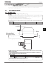
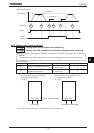
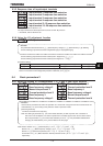
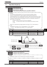
6.3.5 Response time of input/output terminals
H
HH
H : Input terminal 1 response time selection
H
HH
H : Input terminal 2 response time selection
H
HH
H : Input terminal 3 response time selection
H
HH
H : Input terminal 4 response time selection
H
HH
H : Input terminal 5~12 response time selection
H
HH
H : Input terminal 13~20 response time selection
For details, refer to Section 7.2.3.
The output terminal and the response time can be set with “My function.”
For details, refer to Section 6.39.
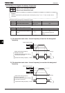
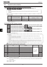
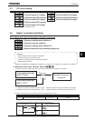
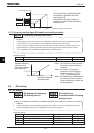
6.3.6 Using the V/f adjustment function
H
HH
H
: V/f adjustment rate
V/f ratio switching (input terminal function 152/153) OFF: Original V/f (
XNX
/
XN
)
V/f ratio switching (input terminal function 152/153) ON: Original V/f
H
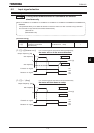
[Parameter setting]
Title Function Adjustment range Default setting
H V/f adjustment rate ~%
Note 1: This function is only effective in the case of RV=0,1.
Note 2: In the case of Overvoltage stall protection is effective, set H=0.
6.4 Basic parameters 2
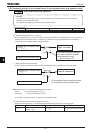
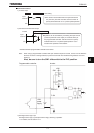
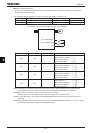
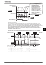
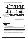
6.4.1 Switching among V/f characteristics 1, 2, 3 and 4 from input terminal
H
HH
H : Base frequency 2
H
HH
H : Base frequency voltage 2
H
HH
H : Manual torque boost 2
H
HH
H : Thermal protection level 2
H
HH
H : Base frequency 3
H
HH
H : Base frequency voltage 3
H
HH
H : Manual torque boost 3
H
HH
H : Thermal protection level 3
H
HH
H : Base frequency 4
H
HH
H : Base frequency voltage 4
H
HH
H : Manual torque boost 4
H
HH
H : Thermal protection level 4
•
Function
Use the above parameters to switch the operation of 4 motors with a single inverter and to select motor V/f
characteristics (1 to 4) according to the particular needs or operation mode.
[Switching methods]
Terminals are used for this switching.
Note:The setting of parameter RV (V/f control mode selection) is valid only when V/f1 is selected. If
V/f2,V/f3 or V/f4 is selected, V/f control is performed in constant torque mode. Do not switch motors
when the parameter RV (V/f control mode selection) is set at , . For parameters selected when
changing V/f characteristics (1 to 4), refer to table on the next page.
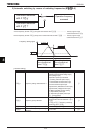
Note: Refer to Section 5. 8 XN (Base frequency 1) for H, H and H,
Section 5. 8 XNX (Base frequency voltage 1) for H, H and H,
Section 5.7 XD (Manual torque boost) for H, H and H,
and Section 5.14 VJT (Motor electronic thermal protection level 1) for H, H and H,
respectively.
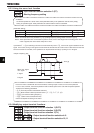
• Function
This parameters reduces the ratio of
XNX
(base frequency vortage 1) /
XN
(base frezuency 1) by selecting
V/f ratio switching (input terminal function 152(positive logic) or 153(negative logic)).