


E6581301
N-2
14
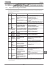
14.2 Periodical inspection
Make a periodical inspection at intervals of 3 or 6 months depending on the operating conditions.
Warning
Mandatory
• Before inspection, perform the following steps.
(1) Shut off all input power to the inverter.
(2) Wait at least 15 minutes and check to make sure that the charge lamp is no longer lit.
(3) Use a tester that can measure DC voltages (800VDC or more), and check that the voltage to the DC
main circuits (between PA/+ and PC/-) does not exceed 45V.
Performing an inspection without carrying out these steps first could lead to electric shock.
Prohibited
• Never replace any part.
This could be a cause of electric shock, fire and bodily injury. To replace parts, call the local sales agency.
■
■■
■ Check items
1. Check to see if all screwed terminals are tightened firmly. If any screw is found loose, tighten it again with a
screwdriver.
2. Check to see if all caulked terminals are fixed properly. Check them visually to see that there is no trace of
overheating around any of them.
3. Check all cables and wires for damage. Check them visually.
4. Clean up dust and soil. With a vacuum cleaner, remove dirt and dust. When cleaning, clean the vents and the
printed circuit boards. Always keep them clean to prevent a damage due to dirt or dust.
5. If no power is supplied to the inverter for a long time, the performance of its large-capacity electrolytic capacitor
declines. When leaving the inverter unused for a long time, supply it with electricity once every two years, for 5
hours or more each, to check the operation of the inverter. Supply electricity for at least 5 hours with the motor
disconnected. It is advisable not to supply the commercial power directly to the inverter but to gradually increase
the power supply voltage with a transformer.
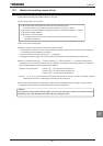
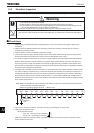
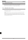
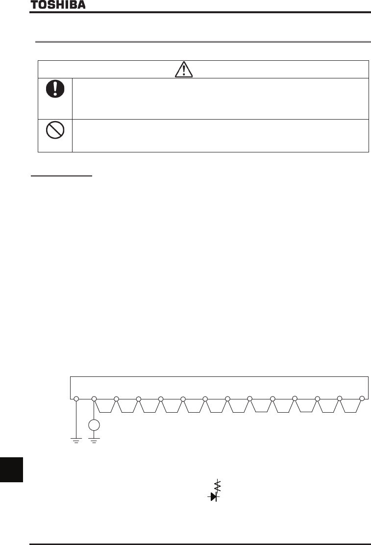
6. If insulation test is needed, conduct it for the main circuit terminal board using a 500V insulation resistance tester
only. Never conduct an insulation test on control terminals other than terminals on the printed circuit board or on
control terminals. When testing the motor for insulation performance, separate it from the inverter in advance by
disconnecting the cables from the inverter output terminals U, V and W. When conducting an insulation test on
peripheral circuits other than the motor circuit, disconnect all cables from the inverter so that no voltage is applied
to the inverter during the test.
Note: •Before an insulation test, always disconnect all cables from the main circuit terminal board and test the
inverter separately from other equipment.
•Switch the grounding capacitor to Small. Refer to 1.3.3
500V insulation
resistance
tester
E R/L1 S/L2 T/L3 U/T1 V/T2 W/T3 PA/+ PO PB PC/- RO SO TO
7. Never test the inverter for pressure. A pressure test may cause damage to its components.
8. Voltage and temperature check
Recommended voltmeter
Input side ... Moving-iron type voltmeter ( )
Output side ... Rectifier type voltmeter ( )
It will be very helpful for detecting a defect if you always measure and record the ambient temperature before,
during and after the operation.