


E6581301
E-9
5
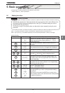
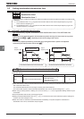
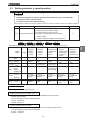
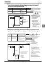
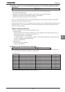
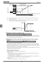
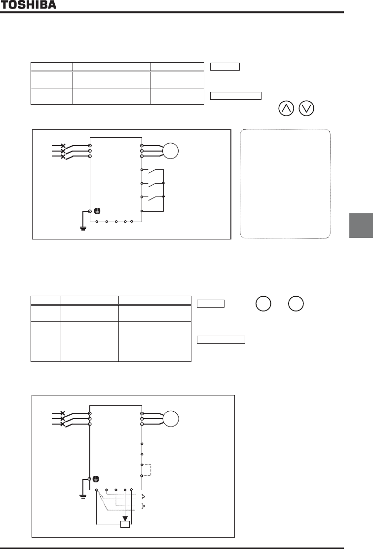
2) Setting the run and stop frequencies (forward run, reverse run and
coast stop) by means of external signals and setting the operation
frequency with the operation panel
Title Function
Example of setting
Run/stop : ON/OFF of terminals F-CC/R-CC
(Standby: connection of terminals
ST and CC)
Speed command : Set the frequency, using
the keys on
the operation panel.
EOQF Command mode selection (Terminal
input)
HOQF Frequency setting mode
selection 1
(Operation
panel input)
Power
supply
Motor
IM
F
R
ST
R/L1
CC
S/L2
T/L3
U/T1
V/T2
W/T3
ON:Forward run,
OFF:Deceleration stop
ON:Reverse run,
OFF:Deceleration stop
ON:Standby,
OFF:Coast stop
Ŭ
The inverter is
factory-
configured so that,
if F and R are
turned on at
the same time, the
inverter will stop
operation. If necessary,
the direction of rotation
can be reversed by
changing parameter
settings.
Refer to Section 6.2.
1
.
Ŭ
To save the frequency,
press the ENTER key.
Then,
HE
and the set
frequency are
displayed alternately
for a while.
CCA RX VI/II
RR/S4
PP
Inverter
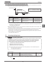
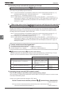
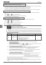
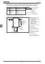
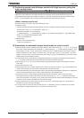
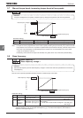
3) Setting the run and stop frequencies (forward run, reverse run and
deceleration stop) with the operation panel and setting the operation
frequency by means of external signals
Title Function Example of setting
Run/stop : Press the and keys on
the operation panel
ŬTo switch between forward run and reverse run,
use the forward/reverse run selection HT.
Speed command : External signal input
(1) VI/II terminal: 0~+10Vdc
(0~+5Vdc) or
4(0)~20mAdc
(2) RR/S4 terminal: Potentiometer
0~+10Vdc (0~+5Vdc)
(3) RX terminal: 0~±10Vdc (0~±5Vdc)
EOQF
Command mode
selection
(Operation panel input)
HOQF
Frequency setting
mode selection 1
(VI/II (voltage/current
input) )
(RR/S4 (potentiometer/
voltage input) )
(RX (voltage input) )
Motor
IM
F
R
ST
R/L1
CC
Shorted by a shorting bar when
shipped from the factory.
(-WN and -HN products.)
Power
supply
S/L2
T/L3
U/T1
V/T2
W/
T3
(1) 0~+10Vdc
(0~+5Vdc)
or 4(0)-20mA
(3) 0~±10Vdc
(0~±5Vdc)
(2) External potentiometer
-
-
+
+
* Other speed setting
: 2-wire RS485 input
: 4-wire RS485 input enabled
: Communication option input
enabled *
: Optional AI1 (differential current
input) *
: Optional AI2 (voltage/current
input) *
: Motor operated pot mop setting
: RP pulse input *
: High-speed pulse input *
: -
*Commands marked with * are
optional. Refer to Instruction Manual
of options described in Section 10.
CCA RX
VI/II
RR/S4
PP
Inverter
RUN
STOP
«
Example of a connection diagram: SW1 set to sink logic
»