


E6581301
F-27
6
XNX
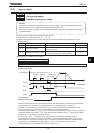
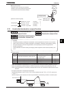
Rated voltage
>1 the output voltage can be
prevented from exceeding
the input voltage.
Note: Rated voltage is fixed for 200V class at 200V and 400V class at 400V.
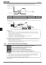
6.14.4 Reverse run prohibition
H
HH
H
: Reverse run prohibition selection
•
Function
This function prevents the motor from running in the forward or reverse direction when it receives the wrong
operation signal.
[Parameter setting]
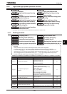
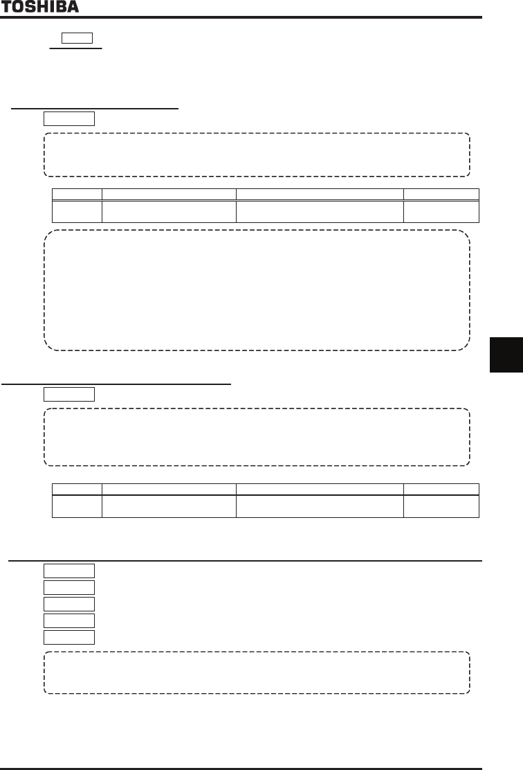
Title Function Adjustment range Default setting
H Reverse-run prohibition selection
:Permit all, :Prohibit reverse run
:Prohibit forward run
Warning
!!
• If an operation command is entered to rotate the motor in the direction prohibited for the preset speed
operation with the mode or forced jog operation, this parameter will cancel the command regardless of
operation mode.
• If the motor constant is not set properly while vector control mode or automatic torque boost mode is
selected, the motor may turn in the reverse direction. T
he number of revolutions that correspond to the slip
frequency, in these modes, therefore, the stop frequency (
H
) should be set at the same level as the
slip frequency. In sensor vector control mode (
RV
=
,
), depending on the setting of
WX
, the motor
restarted may rotate in the direction opposite to the prohibited direction regardless of the setting of this
parameter.
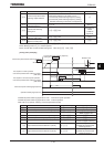
6.14.5 Output voltage waveform selection
H
HH
H
: Output voltage waveform selection
•
Function
It is an effective function only to the capacity of VFAS1-2550P and above, VFAS1-4900PC and above.
The loss of the inverter is reduced a little by setting it to
H
=
, when using it with the career frequency
raised (only as a guide 4kHz and above.
However, some magnetic sounds from the motor is different and use
it after confirming whether there is problem in noise.
[Parameter setting]
Title Function Adjustment range Default setting
H
Output voltage waveform
selection
:PWM carrier frequency control 1
: PWM carrier frequency control 2
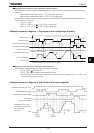
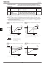
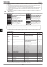
6.15 Drooping control
H
HH
H : Drooping gain
H
HH
H : Speed at drooping gain 0%
H
HH
H : Speed at drooping gain H
HH
H
H
HH
H : Drooping insensitive torque
H
HH
H : Drooping output filter
•
Function
When multiple inverters and motors are used to operate a system, the load can distribute to them using this
function. These parameters allow you to adjust the frequency range, and also insensitive torque and gain.