


E6581301
A-24
1
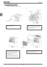
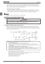
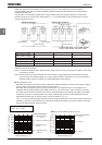
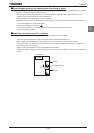
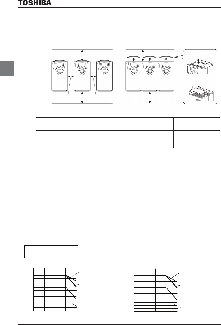
Install the inverter in a well-ventilated indoor place and mount it on a flat metal plate in portrait orientation.
If you are installing more than one inverter, the separation between inverters should be at least 5cm, and they should be
arranged in horizontal rows.
If the inverters are horizontally arranged with no space between them (side-by-side installation), remove of the
protective cover on top of the inverter. (200V-55kW or ODUJHU and 400V-90kW or larger models dose not need to
remove the protective cover)
•
Standard installation
•
Side-by-side installation
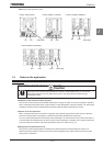
H1 cm or more
H2 cm or more
5cm or more 5cm or more
H3 cm or more
H3 cm or more
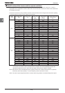
*1 200V 0.4kW~15kW, 400V 0.75kW~18.5kW
*2 200V 18.5kW~45kW, 400V 22kW~75kW
*1
*2
H1(cm) H2(cm) H3(cm)
200V 75kW or smaller
400V 110kW or smaller
10 10 (Note1) 10 (Note1)
400V 132, 160kW 15 15 (Note1) 25 (Note1)
400V 200~280kW 20 15 (Note1) 25 (Note1)
400V 355, 400kW 30 25 (Note1) 25 (Note1)
400V 500kW 40 25 (Note1) 25 (Note1)
The space shown in the diagram is the minimum allowable clearance. Make the space on top and bottom as large as
possible to allow for air passage.
Note1: For models designed for 200V-75kW and 400V-110kW motors or larger, leave a space of 30cm or more above
and below the inverter.
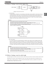
Note2: Do not install in any location where there is high humidity or high temperatures and where there are large
amounts of dust and metallic fragments. If you are going to install the equipment in any area that presents a
potential problem, please consult with your Toshiba distributor before doing so.
■
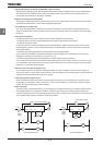
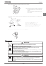
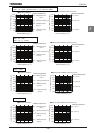
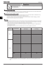
Current reduction curve
Depending on the way in which the inverter is installed, the ambient temperature and the carrier frequency setting,
you may need to reduce the inverter’s continuous output current.
Reduction rates vary depending on the capacity of the inverter. The capacities shown in these diagrams are
capacities with the highest reduction rates. Refer to section 12, you can find 100 % value of output current there.
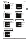
The VFAS1 has the function of adjusting the inverter’s overload resistance automatically according to the ambient
temperature, as shown in the figure below. This function enhances the inverter’s overload resistance when the
ambient temperature is low. To use this function, set the parameter
H to .
If
H is set to (default setting), protection will be provided by reducing the output current (approximate linear
reduction) in
6HFWLRQ
12, “Specifications,” by adjusting the PWM carrier frequency or at the occurrence of the event
shown in the diagram below, which occurs first.
40éᲴW
ithout top cover
F631=1
40éᲴW
ith top cover
(F631=0)
or
50éᲴ
Without top cover
(F631=0)
Ū
Standard installation
100Ჟ
90Ჟ
80Ჟ
70Ჟ
60Ჟ
50Ჟ
Continuous output current
4kHz 8kHz 12kHz 16kHz
Carrier frequency (EH)
40Ჟ
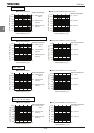
110Ჟ
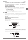
60éᲴ
Without top cover
(F631=0)
Ū
Side-by-side installation (
without top cover
)
100Ჟ
90Ჟ
80Ჟ
70Ჟ
60Ჟ
50Ჟ
Continuous output current
4kHz 8kHz 12kHz 16kHz
Carrier frequency (EH)
40Ჟ
110Ჟ
40éᲴF631=1
50é (F631=0)
60é (F631=0)
400V
0.75
Ŵ
1.5kW
200V
0.4
Ŵ
1.5
Ŵ
7.5kW
Ambient temperature
Ambient temperature