


E6581301
H-2
8
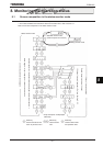
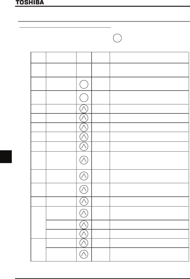
8.2 Monitoring the status
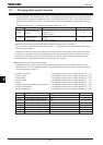
8.2.1 Status monitor under normal conditions
In this mode, you can monitor the operation status of the inverter.
To monitor the inverter when it is normally running, press the key
twice
and the current status is indicated
on the LED display.
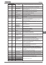
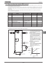
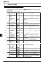
Setting procedure (EX.: operation at 60 Hz)
Commun
ication
No.
Item displayed
Key
operated
LED
display
Description
-
Standard monitor
mode
The output frequency is displayed (during operation).
(When standard monitor display selection H is set
to [Output frequency])
FE01
Setting monitor
mode
CWJ
The first basic parameter “History function (CWJ)” is
displayed.
FE01
Status monitor mode
(Rotating direction)
HTH
The rotating direction is displayed. (H:Forward run,
T:Reverse run)
-
Frequency
command value
The operation frequency command value is displayed.
(When H=, Frequency command)
- Output current E
The inverter output current (load current) is displayed.
(When H=, Output current)
-
Input voltage (DC
detection)
[
The Inverter DC voltage (default setting: unit %) is
displayed.(When H=, Input voltage) [Note 3]
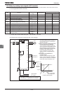
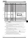
- Output voltage R
The inverter output voltage (default setting: unit %) is
displayed.(When H=, output voltage)
- Torque S
The torque is displayed.
(When H= torque)
-
Regenerative
braking resistance
overload factor
(PBrOL data)
T
The regenerative braking resistance overload factor is
displayed.
(When H=, regenerative braking resistance
overload factor)
-
Inverter overload
factor
(OL1 data)
I
The inverter overload factor is displayed.
(When H=, inverter overload factor)
-
Motor overload
factor
N
The motor overload factor (default setting: unit %) is
displayed.
(When H=, Motor overload factor)
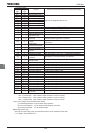
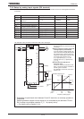
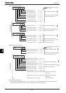
FE00 Output frequency The output frequency is displayed.
FE06
Input terminal
information 1
The ON/OFF status of each of the control signal input
terminals (F, R, ST, RES, S1, S2, S3, RR/S4) is
displayed in bits.
Input terminal
information 2
C
The ON/OFF status of each of the optional control signal
input terminals (LI1, LI2, LI3, LI4) is displayed in bits.
Input terminal
information 3
D
The ON/OFF status of each of the optional control signal
input terminals (LI5, LI6, LI7, LI8) is displayed in bits.
FE07
Output terminal
information 1
The ON/OFF status of each of the control signal output
terminals (OUT1, OUT2, FL) is displayed in bits.
Output terminal
information 2
The ON/OFF status of each of the optional control signal
output terminals (OUT3, OUT4, R1, OUT5, OUT6, R2,
R3, R4) is displayed in bits.
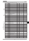
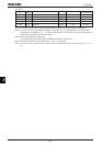
(Continued overleaf)
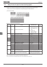
*1
MODE
*2
*3
*4
MODE
*5
*7
*8
*9
*6
MODE
[Note 4]