


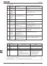
E6581301
M-5
13
(Continued)
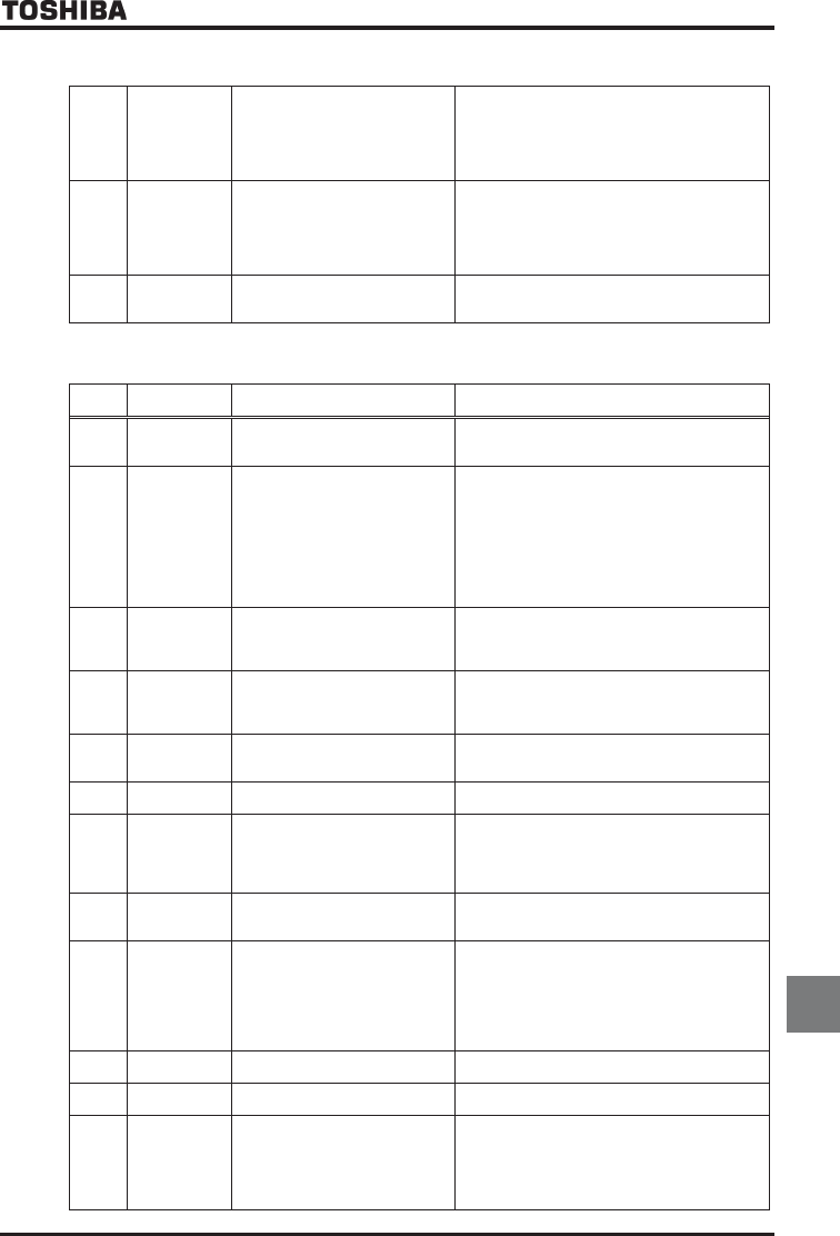
G
Internal circuit
error
•Motor control CPU is defective.
•The drive circuit board in the
inverter was damaged.
•Power device is defective.
•Using braking function in not
RV=,,,, mode
•Contact your Toshiba distributor.
•If the braking function is used, operate a motor in
RV=,,,, mode
G
Control power
backup
undervoltage
error
•The control voltage between +SU
and CC terminals is too low.
•Control power is not supplied
through +SU and CC terminals.
•The parameter H is not set
correctly.
•Check whether the voltage between +SU and CC
terminals is DC20V or more.
•Set H to 0 if a control power backup device
is not connected to +SU and CC terminals.
To reset the inverter that has been tripped
because of this error, turn it off and then back on.
UQWV
Step-out (for
PM motors
only)
•The motor shaft is locked.
•One output phase is open.
•An impact load is applied.
•Unlock the motor shaft.
•Check the interconnect cables between the
inverter and the motor.
Note: Please contact us if you find any trips other than the above.
[Alarm] The following are messages only. No trip is developed.
Error
code
Problem Possible causes Remedies
QHH
ST signal OFF
•ST terminal is in open-circuit. •Check SW1 select
•Close ST-CC circuit (Sink logic)
•Close ST-P24/PLC circuit (Source logic)
EQHH
Control power
backup
undervoltage
•The control voltage between +SU
and CC terminals is too low.
•Control power is not supplied
through +SU and CC terminals.
•The parameter H is not set
correctly.
•Check whether the voltage between +SU and CC
terminals is DC20V or more.
•Set H to if a control power backup device
is not connected to +SU and CC terminals.
In the event of a EQHH error, the inverter will not
be reset automatically even if the control voltage
between +SU and CC terminals returns to its
normal level. To reset the inverter, turn it off and
then back it on.
OQHH
Undervoltage in
main circuit
•The supply voltage between R, S
and T is under voltage.
•Trouble of rush current restraint
circuit or DC circuit fuse.
•Measure the main circuit supply voltage.
If the voltage is at a normal level, the inverter
requires repairing.
•Contact your Toshiba distributor.
TVT[
Retry
•The inverter is in the process of
retry.
•A momentary stop occurred.
•The inverter is normal if it restarts after several
tens of seconds. The inverter restarts
automatically. Be careful of the machine because
it may suddenly restart.
GTT
Point setting
alarm
•The frequency setting signals at
points 1 and 2 are set too close to
each other.
•Set the frequency setting signals at points 1 and 2
apart from each other.
G
Key failure
alarm
•
The same key is input continuously
more than 20 seconds.
•Check the operation panel.
ENT
Clear enabling
indication
•This message is displayed when
pressing the STOP key while an
error code is displayed.
• Input terminal RES signal is ON
during trip display.
•Press the STOP key again to clear the trip.
•Turn off the input terminal RES signal.
GQHH
Emergency stop
enabling
indication
•The operation panel is used to
stop the operation in automatic
control or remote control mode.
•Press the STOP key for an emergency stop. To
cancel the emergency stop, press any other key.
JK/N
Setting error
alarm
An error code
and data are
displayed
alternately twice
each.
•An error is found in a setting when
data is reading or writing.
•Check whether the setting is made correctly.
FD
DC braking
•DC braking in process
•Field forcing in process
•The message goes off in several tens of seconds
if no problem occurs. [Note]
FDQP
Shaft fixing in
control
•Motor shaft fixing control is in
process.
•If the message disappears by stop command
(ST-CC open), it is normal.
G
G
G
Panel indication
overflow
•The digit number of the item
displayed, e.g., frequency, is in
excess of the specified digit
number.
(Number of overflowing digits is
indicated.)
•For indication of frequency, set multiplying rate
(H) lower. (Parameter setting that results in
overflow is of course valid.)