


E6581301
I-5
9
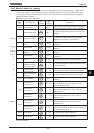
(Continued)
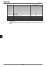
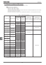
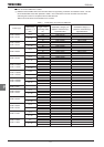
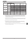
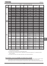
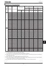
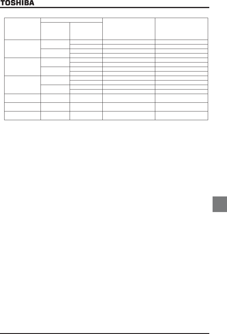
Inverter type
Requirements
Conducted noise
IEC61800-3 category C2
(EN55011 classA Group1)
Applicable filters
Conducted noise
IEC61800-3 category C1
(EN55011 classB Group1)
Applicable filters
PWM carrier
frequencyEH
(kHz)
Length of motor
connecting cable
(m)
VFAS1-4220PL
2~4
100 EMF3-4090F EMF3-4090F
300 EMF3-4090F -
4.1~12
100 EMF3-4090F EMF3-4090F
200 EMF3-4090F -
VFAS1-4300PL
VFAS1-4370PL
2~2.5
100 EMF3-4092G EMF3-4092G
300 EMF3-4092G -
2.6~12
100 EMF3-4092G EMF3-4092G
200 EMF3-4092G -
VFAS1-4450PL~
VFAS1-4750PL
2~2.5
100 EMF3-4180H EMF3-4180H
300 EMF3-4180H -
2.6~12
100 EMF3-4180H EMF3-4180H
200 EMF3-4180H -
VFAS1-4900PC~
VFAS1-4132KPC
2.5 100 EMF3-4300I -
VFAS1-4160KPC~
VFAS1-4280KPC
2.5 100 EMF3-4600J -
VFAS1-4355KPC~
VFAS1-4500KPC
2.5 100 EMF3-4600J × 2 -
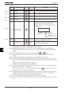
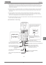
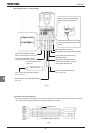
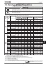
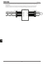
(2) Use shielded cables for the power and control cables, including filter input cables and inverter output cables.
Route the cables and wires so as to minimize their lengths. Keep a distance between the power cable and the
control cable and between the input and output wires of the power cable. Do not route them in parallel or bind
them together, instead cross at right angle.
(3) Install the filter and the inverter in an enclosed steel cabinet, it is more effective in limiting the radiation. Earth the
cabinet body securely with the thickest and shortest possible electric wire installed away from the power cables.
(4) Route the EMC filter input and output wires apart from each other.
(5) To limit the radiation noise from cables, earth each shielded cable to the EMC plate. It is effective to earth
shielded cables in the vicinity of the inverter and filter (within a radius of 10cm from each of them). Inserting a
ferrite core in a shielded cable is even more effective in limiting the radiation noise.
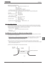
(6) To further limit the radiation noise, insert a zero-phase reactor in the inverter output line and insert ferrite cores in
the earth cables of the EMC plate and cabinet.