


E6581301
F-10
6
■
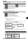
Setting of switching terminals
The V/f1, V/f2, V/f3 and V/f4 switching function is not yet assigned to any terminal. Therefore, it is necessary to
assign them to unused terminals.
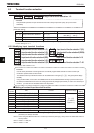
Ex.) Assigning the V/f switching 1 function to S1 and the V/f switching 2 function to S2.
Title Function Adjustment range setting value
H Input terminal function selection 5 (S1) ~ (V/f switching 1)
H Input terminal function selection 6 (S2) ~ (V/f switching 2)
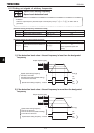
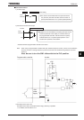
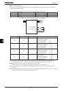
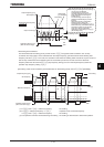
«An example of the connection of terminals: SW1 set to sink logic»
S1: V/f switching 1
S2: V/f switching 2
CC
M
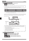
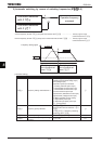
S1-CC S2-CC V/f Parameters selected
OFF OFF 1
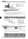
Base frequency 1 : XN
Base frequency voltage 1 : XNX
Manual torque boost 1 : XD
Thermal protection 1 : VJT
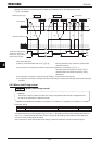
ON OFF 2
Base frequency 2 : H
Base frequency voltage 2 : H
Manual torque boost 2 : H
Thermal protection 2 : H
OFF ON 3
Base frequency 3 : H
Base frequency voltage 3 : H
Manual torque boost 3 : H
Thermal protection 3 : H
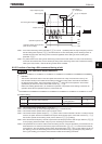
ON ON 4
Base frequency 4 : H
Base frequency voltage 4 : H
Manual torque boost 4 : H
Thermal protection 4 : H
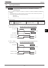
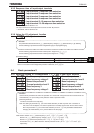
Note1:V/f switching is not able to change during the inverter running,. Always stop the inverter and then switch.
It is necessary to wait for 0.1 second and over until start up inverter from switch the V/f switching.
Note2:Select V/f1 when using the vector control and the V/f-5 point setting.
Selecting V/f2,.V/f3, or V/f4 disables vector control but enables the V/f constant control.
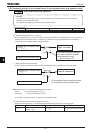
Note3:By using “My function,” torque limits and acceleration/deceleration modes can be switched along with V/f
switching.
Note4:With the operation panel or communication, the panel acceleration/deceleration selection (H) can be set.
* This function is active only in operation panel operation mode.