


E6581301
G-4
7
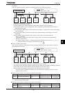
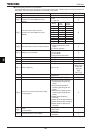
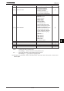
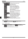
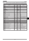
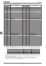
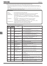
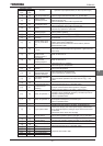
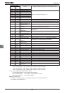
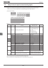
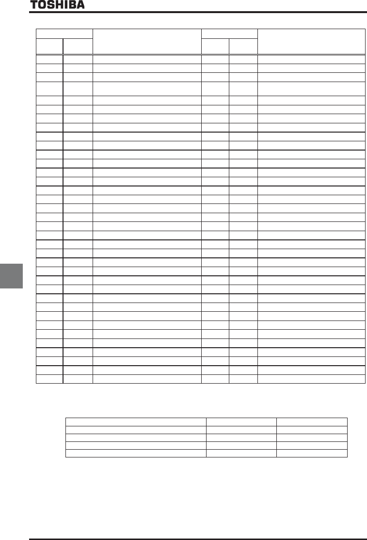
■ Table of setting of contact input terminal function
Parameter setting
Function
Parameter setting
Function
Positive
logic
Negative
logic
Positive
logic
Negative
logic
No function is assigned
Simple positioning (positioning loop)
F: Forward run command
Integrating wattmeter display clear
R: Reverse run command
Trace back trigger signal
ST: Standby
Light-load high-speed operation
prohibitive signal
RES: Reset
No function assigned
S1: Preset speed 1
No function assigned
S2: Preset speed 2
No function assigned
S3: Preset speed 3
Binary data write
S4: Preset speed 4
Motor operated pot mop set (up) *1
Jog run
Motor operated pot mop set (down) *1
Emergency stop
Motor operated pot mop set (clear)
DC braking
No function assigned
Acceleration/deceleration switching 1 *2
No function assigned
Acceleration/deceleration switching 2 *2
Forward/reverse selection
V/f switching signal 1
*2
Run/stop command
*3
V/f switching signal 2
*2
Commercial power/INV switching
Torque limit switching signal 1
*2
Frequency reference priority switching
Torque limit switching signal 2
*2
VI/II terminal priority
PID control OFF selection
Command terminal board priority
Pattern operation group 1
Permission of parameter editing
Pattern operation selection 2
Speed/Torque switching
Pattern operation continuation signal
No function assigned
Pattern operation trigger signal
No function assigned
External thermal error
No function assigned
Communication priority cancel
No function assigned
HD operation retention
Rapidest deceleration command
PID differentiation/integration clear
Preliminary excitation
*4
PID forward/reverse switching
Braking request
Forced continuous operation
No function assigned
Specified speed operation
Brake answer back input
Acceleration/deceleration suspend signal
No function assigned
Power failure synchronized signal
Traverse permission signal
My function RUN signal
(reservation)
Auto-tuning signal V/f ratio switching
Speed gain switching Manual torque boost switching signal
Servo lock signal
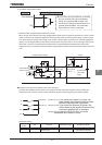
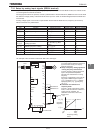
*1: Valid when HOQF(Frequency setting mode selection 1) is set at (Motor operated pot mop setting).
The frequency setting range is between =~WN(Upper limit frequency). The acceleration/deceleration time with respect
to the frequency setting remains CEE/FGE, unless switching between acceleration and deceleration is performed.
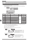
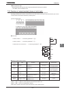
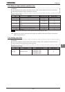
*2: To switch acceleration/deceleration pattern, V/f pattern, torque limit 1~4, give the following signals to switching functions.
Switching signal 1 Switching signal 2
Acceleration/deceleration1, V/f 1, torque limit 1 OFF OFF
Acceleration/deceleration2, V/f 2, torque limit 2 ON OFF
Acceleration/deceleration3, V/f 3, torque limit 3 OFF ON
Acceleration/deceleration4, V/f 4, torque limit 4 ON ON
*3: If , (F: Forward run command) or , (R: Reverse run command) is assigned at the same time, this function has a
priority.
*4: After the motor slows down and comes to a full stop at a pre-excitation command, the motor is set free momentarily to
bring it into a pre-excitation state.
This function should not be used when H is set to or . Or the inverter might malfunction.
*5: Do not set the function " Permission of parameter editing" into the parameter H~H (without option)
and~H. If it is setted, can not reset the setting.