


E6581301
F-76
6
■
■■
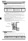
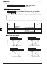
■ Example of setting 1
Set H=[Hz]:
Each time you press the key, Each time the frequency setting HE changes in steps of 10.0Hz: 0.0
→
10.0
→
20.0
→
...
→
60.0 [Hz]. This function comes in very handy when operating the load at limited frequencies that
change in steps of 1 Hz, 5Hz, 10Hz, and so on.
■
■■
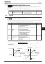
■ Example of setting 2
Set H=[Hz], H=:
Each time you press the key, the frequency setting HE changes in steps of 1 Hz: 0
→
1
→
2
→
...
→
60
[Hz] and also the value displayed on the operation panel changes in steps of 1. Use these settings to hide
decimal fractions. And also the value displayed on the operation panel changes in steps of 1. Use these settings
to hide decimal fractions.
6.36.4 Changing the standard monitor display
H
HH
H : Standard monitor display selection
H
HH
H ~ H
HH
H : Status monitor 1~8 display selection
These parameters are used to select the item to be displayed when the power turned on and also to change items
displayed in status monitor mode. For details, refer to Section 8.3.
6.36.5 Canceling the operation command
H
HH
H : Operation command clear selection
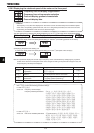
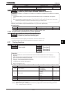
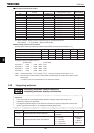
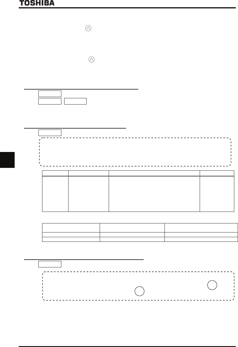
Title Function Adjustment range Default setting
H
Operation command
clear selection
0ᲴWhen standby terminal (ST) is OFF, clear panel
operation command
1ᲴWhen standby terminal (ST) is OFF, remain
operation command
2ᲴWhen standby terminal (ST) is OFF or
undervoltage alarm occurs, clear panel and
communication (RS485 & option) operation
command.
To retain or clear operation command by setting H are shown in below table.
Panel operation command
Communication (RS485 & option)
operation command
Standby terminal (ST) is OFF 0Ჴclear 1Ჴretain 2Ჴclear 0Ჴretain 1Ჴretain 2Ჴclear
Undervoltage alarm 0Ჴretain 1Ჴretain 2Ჴclear 0Ჴretain 1Ჴretain 2Ჴclear
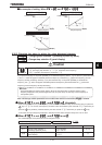
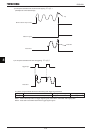
6.36.6 Selection of operation panel stop pattern
H
HH
H : Operation panel stop pattern selection
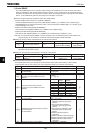
1) Deceleration stop
The motor stops in the deceleration time set with the parameter FGE (or H, H).
2) Coast stop
The output of the inverter is cut off. The motor comes to a stop after coasting for a while by inertia. Depending on
the load, the motor may keep running for a good long time.
[Parameter setting]
•
••
• Function
This parameter are used to select a mode in which the motor started by pressing the
RUN
key
on the operation panel is stopped when the
STOP
key is pressed.
•
••
•
Function
You can use this function when driving with the RUN key on the operation panel.
When it turns on again after turning off the input terminal which assigned the standby ”ST” function(Refer to
7.2.1) during driving the inverter, the inverter will drive again without pushing the RUN key.
Using this function, the inverter is not driven again unless the RUN key is pushed on after turning on the ST signal.