


E6581301
F-80
6
■
■■
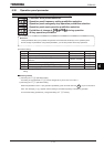
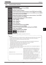
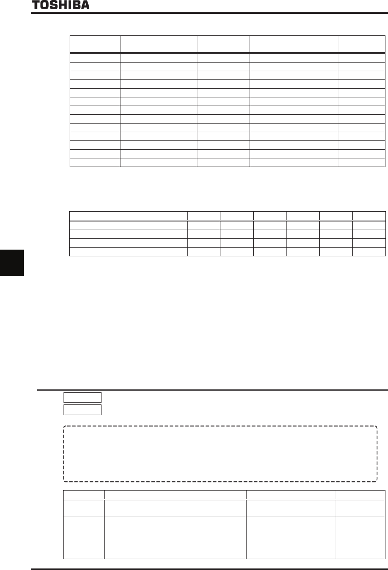
■ Trace data communication number
Communication
No.
Function
Minimum setting
/readout unit
Setting/readout range Default setting
E000 Trace data 1~4 pointer / ~
E100 Data 1 of trace data 1 / ~HHHH
Data 2~99 of trace data 1 / ~HHHH
E199 Data 100 of trace data 1 / ~HHHH
E200 Data 1 of trace data 2 / ~HHHH
Data 2~99 of trace data 2 / ~HHHH
E299 Data 100 of trace data 2 / ~HHHH
E300 Data 1 of trace data 3 / ~HHHH
Data 2~99 of trace data 3 / ~HHHH
E399 Data 100 of trace data 3 / ~HHHH
E400 Data 1 of trace data 4 / ~HHHH
Data 2~99 of trace data 4 / ~HHHH
E499 Data 100 of trace data 4 / ~HHHH
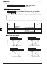
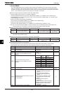
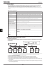
Ex.) When operation frequency data is acquired through a communication device
Data acquired (H) h=8000 8000×0.01Hz=80.0Hz
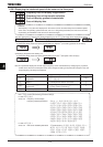
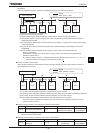
■ Relationship between pointer and data
The table below shows the relationship between pointer (E000 set value) and trace data (1 to 4).
Pointer (E000 set value) ~
Trace data 1ᲢE100᳸E199Უ E100 E101 E102 ~ E198 E199
Trace data 2ᲢE200᳸E299Უ E200 E201 E202 ~ E298 E299
Trace data 3ᲢE300᳸E399Უ E300 E301 E302 ~ E398 E399
Trace data 4ᲢE400᳸E499Უ E400 E401 E402 ~ E498 E499
<Example of setting> If E000 is set to :
(Earliest data) (Latest data)
Trace data 1 E102 ~ E199, E100, E101
Trace data 2 E202 ~ E299, E200, E201
Trace data 3 E302 ~ E399, E300, E301
Trace data 4 E402 ~ E499, E400, E401
Note 1: Use the parameters H through Hto specify the types of trace data (1 to 4).
Note 2: Communication numbers E000 is automatically incremented by the inverter when data is traced
continuously.
* In ordinary cases, these parameters do not need to be rewritten.
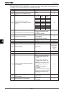
6.38 Integrating wattmeter
H
HH
H
: Integrating wattmeter retention selection
H
HH
H
: Integrating wattmeter display unit selection
•
••
• Function
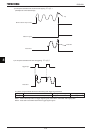
At the main power off ,it is selectable whether retention of integral output power values or not.
And also, the display unit is selectable.
The integrating wattmeter display can be cleared by external input signal by assignment of the terminal
function. Input terminal function 74, 75 (Integrating wattmeter display clear)
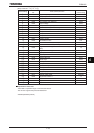
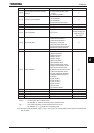
Title Function Adjustment range Default setting
H Integrating wattmeter retention selection
: Disabled
: Enabled
H Integrating wattmeter display unit selection
: 1 = 1 kWh
: 1 = 10 kWh
: 1 = 100 kWh
: 1 = 1000 kWh
: 1 = 10000 kWh
Accoding to
model
Refer to
page K-48.