


E6581301
M-8
13
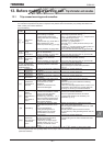
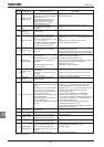
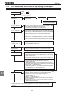
13.3 If the motor does not run while no trip message is displayed...
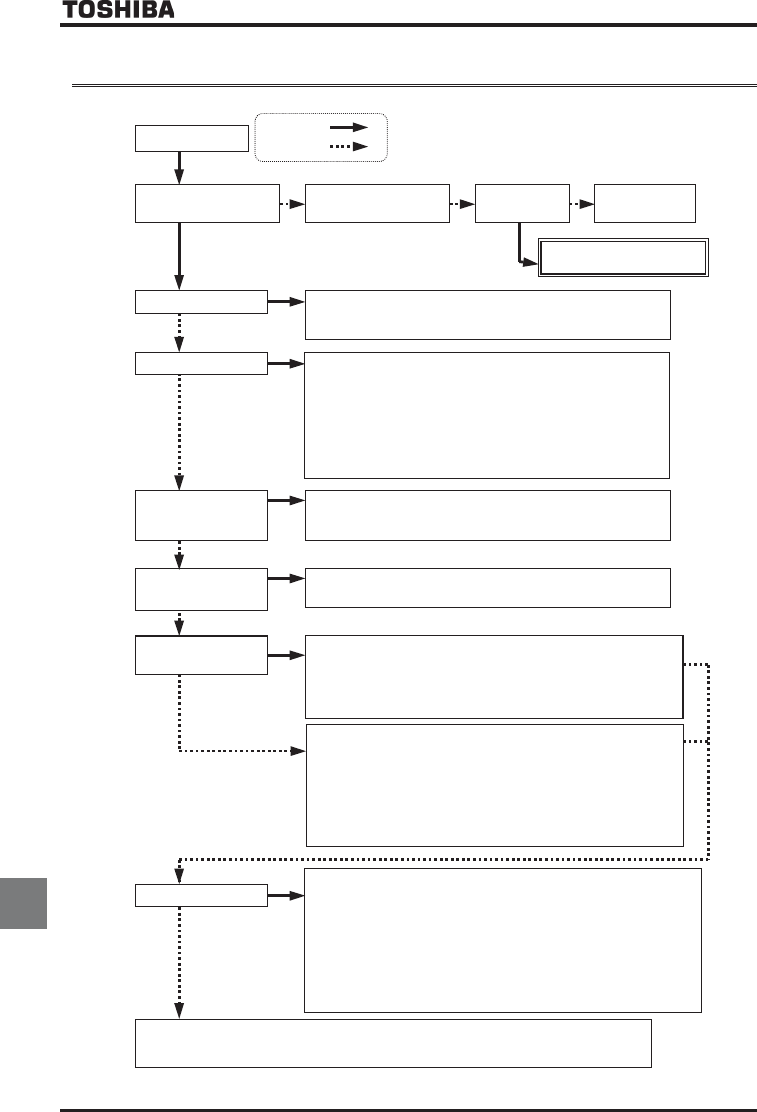
If the motor does not run while no trip message is displayed, follow these steps to track down the cause.
The motor does not run.
Is the 7-segment LED
extinguished?
Check the power supply
and the MCCB.
Is power being
supplied normally?
Supply the power
normally.
• Check the cooling fan.
•
Contact your Toshiba distributor
.
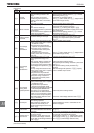
Is
OQHH
blinking?
Main circuit power is undervoltage. Check the input
voltage. If a DC
reactor (DCL) is connected, check also its wiring.
For monitoring input voltage, refer to Section 8.2.1.
Is
QHH
displayed?
•
Check whether a control terminal circuit board is connected to the inverter.
•
When sink logic is enabled
(SW1: SINK), no connection is established
between ST and CC. Close the circuit between CC and the terminal to
which the ST (standby) function on the control circuit terminal is
assigned.
Refer to section 7.2.1.
•
When source logic is enabled (SW1: SOURC
E), no connection is established
between ST and P24. Establish a connection between P24 and the terminal
on the control terminal board to which the ST (standby) function is assigned.
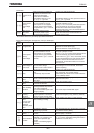
Is any failure message
displayed?
Refer to Section 13.1.
Track down and eliminate the cause
of the failure and then reset the
inverter.
For resetting, refer to Section 13.2.
Are
TVT[
and a
failure message
displayed alternately?
The inverter is in the process of retrying. The retry function can be disabled
by normal or emergency stop operation, or by turning off the inverter.
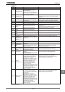
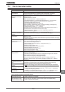
RUN key lamp lighted?
•
Check to see that the f
requency setting signal is not set at zero.
•
Check the settings of the frequency setting signal parameters
HOQF
,
H
,
H
and
H
.
Refer to Section 5.5.
•
Check the frequency setting signal points 1 and 2 settings.
Refer to Section 7.3.
•
Check that the start-up frequency is not higher than the operation
frequency.
Refer to Section 6.7.
•
Check that the frequency setting (preset-speed operation frequency,
etc.) is not set at zero.
•
Check that the motor is not under a too large load or not locked up.
→
Reduce the load if necessary.
Determine the cause, using the parameter display function and the status monitoring function.
Refer to Section 11 for the parameter display function or Section 8 for the status motoring
function.
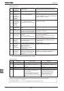
•
When operation panel operation is selected ... Press the RUN key to
start the operation.
•
Check whether the operation panel operation frequency is set properly.
Refer to Section 3.2.2.
•
If another operation mode is selected ... Change the setting of the
command mode selection parameter
EOQF
.
Refer to Section 5.5.
YES :
NO :
•
If the control panel operation mode is selected ... Change the setting
of the command mode selection parameter
EOQF
to
.
Refer to Section 5.5.
•
In other operation mode ... Check whether the external operation
command is entered.
Setup status of input terminals can be checked
by the monitor.
Refer to Section 8.1.
•
Check setup contents of
H
parameter (selection of operation
to which priority is given when forward/reverse run commands are
input simultaneously).
Refer to Section 6.2.1.
Is
displayed?