


E6581301
E-29
5
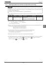
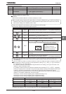
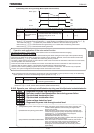
[Terminal AM-related parameters]
Title Function Adjustment range Default setting
COUN AM terminal meter selection Same as HOUN (:AM output disabled)
CO AM terminal meter adjustment – *1
H
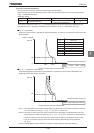
AM output gradient
characteristic
: Negative gradient (downward-sloping),
: Positive gradient (upward-sloping)
H AM bias adjustment –~ %
*1: Default setting value is adjusted for connection of frequency meters "QS60T".
(Between AM and CCA: Approx. 3.6V)
■
■■
■ Resolution
Both the terminals FM and AM have a maximum resolution of 1/1024.
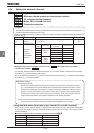
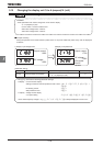
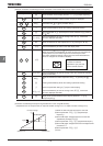
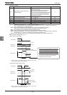
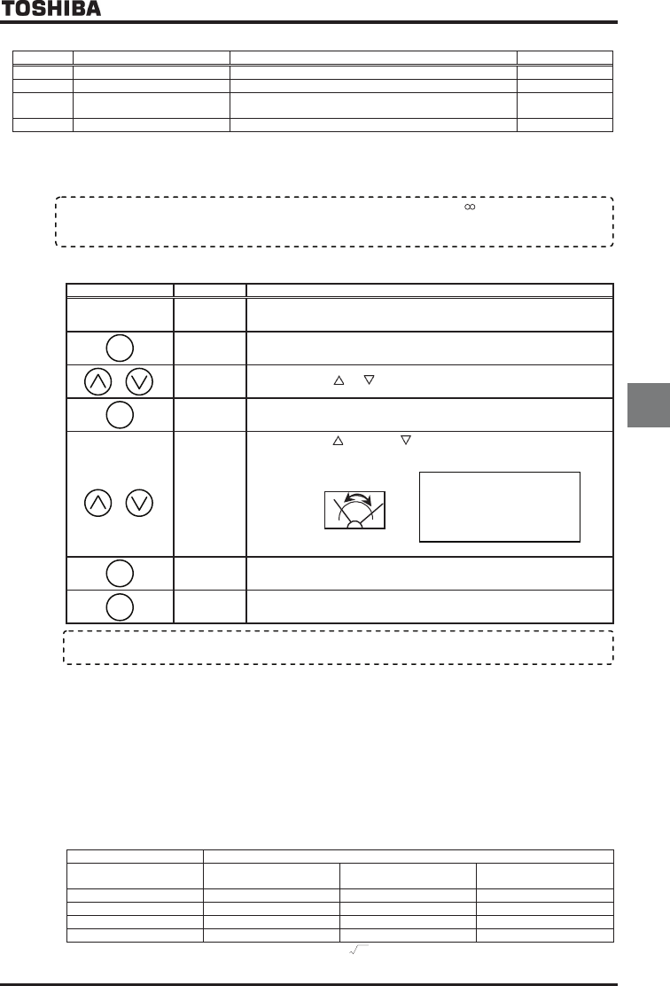
[Example of the calibration of the frequency meter connected to the terminal FM]
* Use the meter's adjustment screw to pre-adjust zero-point.
Key operated LED display Operation
–
Displays the operation frequency.
(When standard monitor display selection H= [Output frequency])
CWJ
The first basic parameter “History function (CWJ)” is displayed.
HO
Press either the or key to select “HO.”
Press the ENTER key to display the operation frequency.
Press either the key or the key to adjust the meter.
The meter reading will change at this time but be careful because there
will be no change in the inverter's digital LED (monitor) indication.
ŬBy setup, before the needle of meter beings to sway, it will take time.
⇔HO
The adjustment is complete. HO and the frequency are displayed
alternately.
The display returns to its original indications.
(When standard monitor display selection H= [Output frequency])
■
■■
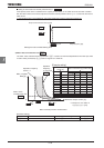
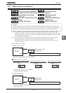
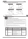
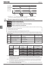
■ Meter adjustment 1 when the inverter is at rest (adjustment by setting HOUN (COUN) to : Fixed output 1,
: Fixed output 2, : Fixed output 3)
If it is difficult to calibrate a meter because of large fluctuations of its reading, you may put the inverter out of
operation to make its calibration easier.
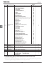
It is possible to adjust the meter for the data item selected with the parameter HOUN or COUN. Adjustment
levels (a) through (d) shown in the table on the previous page change according to the settings of fixed outputs
1 through 3, as shown in the table below. Use this table as a reference when calibrating the meter(s).
Values adjusted with fixed outputs are put out from the FM (AM) terminal when values in the table are used for
operation. For examples of adjustments, see the next page.
Fixed output 1 comes in handy for adjusting items at adjustment level (a) or (c).
Fixed output 2 comes in handy for adjusting items at adjustment level (b).
Fixed output 3 comes in handy for adjusting items at adjustment level (d).
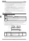
Meter adjustment
Adjustment level
Fixed output 1
HOUN(COUN)Ჷ
Fixed output 2
HOUN(COUN)Ჷ
Fixed output 3
HOUN(COUN)Ჷ
(a) HJ*2 54% 40%
(b) 185% 100% 74%
(c) 150% 81% 60%
(d) 250% 135% 100%
*1: The 100% value of input/output power is the product of
3
×200V (400V) × inverter’s rated current.
*2: When HOUN(COUN)=,,~,~,~, fixed output level is 100%.
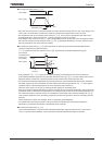
ŬFor meter connection, the VF-PS1 inverter has two output terminals; FM and AM, which can be used
simultaneously.
ŬWith the default settings, FM terminal outputs about 4.7V (external impedance is
) or about 1mA (external
impedance is 0), when running frequency is 80Hz. AM terminal outputs about 4.7V or about 1mA, when the
output current reading on the operation panel is 185%.
MODE
ENT
ENT
MODE
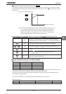
[Hint]
It's easier to make the
adjustment if you push and
hold for
several seconds.