


E6581301
11
K-16
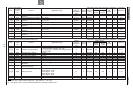
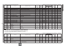
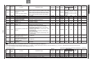
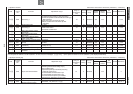
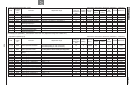
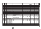
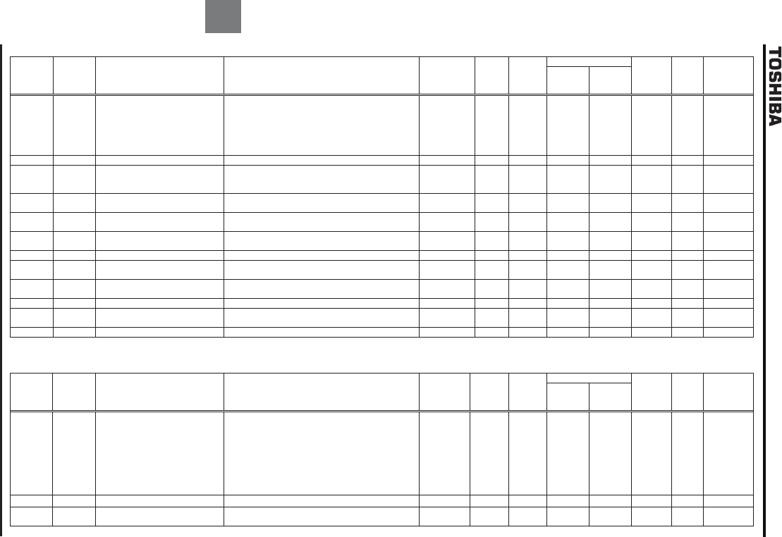
[18] Motor constant Sensorless vector/vector with sensor (Ɣ:Effective, -:Ineffective)
Title
Communi
cation
No.
Function Adjustment range
Minimum
setting unit
(Panel/Communi
cation)
Default
setting
Write during
running
Vector control
PM
control
V/f Constant
Reference
Speed
control
Torque
control
H
0400 Auto-tuning 1
0:No auto
-
tuning
1:Initialize motor constant (0 after execution)
2:Continue operation continued after auto-tuning (0
after execution)
3:Auto-tuning by input terminal signal
4:Motor constant auto calculation (0 after
execution)
1/1 0 Disabled Ɣ/Ɣ Ɣ/Ɣ - - 6. 22
H
0401
Slip frequency gain
0~150
%
1
/1
7
0
Enabled
Ɣ
/
-
-
-
-
6. 22
H
0402 Auto-tuning 2
0:
Disabled
1:Self-cooled motor
2
:Forced air
-
cooled motor
1/1 0 Disabled Ɣ/Ɣ Ɣ/Ɣ - - 6. 22
H
0405
Motor rated capacity (motor
name plate)
0.10~630.0kW 0.01/0.01 *1 Disabled Ɣ/Ɣ Ɣ/Ɣ - - 6. 22
H
0406
Motor rated current (motor
name plate)
0.1~2000A 0.1/0.1 *1 Disabled Ɣ/Ɣ Ɣ/Ɣ - - 6. 22
H
0407
Motor rated
rotational speed
(motor name plate)
100~60000min-1 *2 1/1 *1 Disabled Ɣ/Ɣ Ɣ/Ɣ - - 6. 22
H
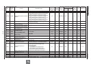
0410
Motor constant 1 (torque boost)
0.0~30.0%
0.1
/0.1
*1
Enabled
Ɣ
/
Ɣ
Ɣ
/
Ɣ
-
-
6. 22
H
0411
Motor constant 2 (no load
current)
10~90% 1/1 *1 Disabled Ɣ/Ɣ Ɣ/Ɣ - - 6. 22
H
0412
Motor constant 3 (leak
inductance)
0~250(g0.1%) 1/1 *1 Disabled Ɣ/Ɣ Ɣ/Ɣ - - 6. 22
H
0413
Motor constant 4 (rated slip)
0.
1
~
25
.0%
0.1
/0.1
*1
Disabled
Ɣ
/
Ɣ
Ɣ
/
Ɣ
-
-
6. 22
H
0415
Exciting strengthening
coefficient
100~130% 1/1 100 Disabled Ɣ/Ɣ Ɣ/Ɣ - - 6. 23
H
0416
Stall prevention factor
10~250
1/1
100
Disabled
Ɣ
/
Ɣ
Ɣ
/
Ɣ
-
-
6. 23
*1: Default values vary depending on the capacity. See the table of K-48.
*2: If the speed of rotation is set at 10,000min
-1
or more, the error messages and G (if the speed of rotation is set at 10,000min
-1
) are displayed alternately.
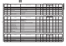
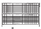
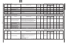
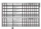
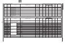
[19] Torque control [1/2] Sensorless vector/vector with sensor (Ɣ:Effective, -:Ineffective)
Title
Communi
cation
No.
Function Adjustment range
Minimum
setting unit
(Panel/Communi
cation)
Default
setting
Write during
running
Vector control
PM
control
V/f Constant
Reference
Speed
control
Torque
control
H
0420 Torque command selection
1:VI/II (voltage/current input)
2:RR/S4 (potentiometer/voltage input)
3:RX (voltage input)
4:Operation panel input enabled (including
LED/LCD option input)
5:2-wire RS485 communication input
6:4-wire RS485 communication input
7:Communications option input enabled
8:Optional AI1 (differential current input)
1/1 3 Enabled - Ɣ/Ɣ - - *1
H
0421 Torque reference filter 0~1000ms
1/1 0
Enabled - Ɣ/Ɣ - - *1
H
0423
Tension torque bias input
selection (torque control)
0:Disabled, 1~8 (same as H) 1/1 0 Enabled - Ɣ/Ɣ - - 6. 24. 3
*1: For details, refer to Instruction Manual (E6581331) specified in Section 6.42.