


E6581301
A-20
1
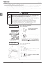
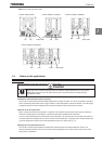
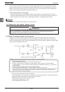
There is no fuse in the inverter's main circuit. Thus, as the diagram above shows, when more than one inverter is
used on the same power line, you must select interrupting characteristics so that only the MCCB2 will trip and the
MCCB1 will not trip when a short occurs in the inverter (INV1). When you cannot select the proper characteristics
install a circuit interrupting fuse between the MCCB2 and the INV1.
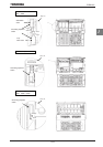
If power supply distortion is not negligible
If the power supply distortion is not negligible because the inverter shares a power distribution line with other
systems causing distorted waveforms, such as systems with thyristers or large-capacity inverters, install an input
reactor to improve the input power factor, to reduce higher harmonics, or to suppress external surges.
■
■■
■ Disposal
If an inverter is no longer usable, dispose of it as industrial waste.
1.4.3 Measure to take against leakage Current
Caution
Current may leak through the inverter's input/output wires because of insufficient electrostatic capacity on the motor with bad
effects on peripheral equipment. The leakage current's value is affected by the carrier frequency and the length of the
input/output wires. Test and adopt the following remedies against leakage current.
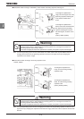
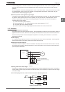
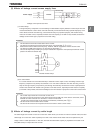
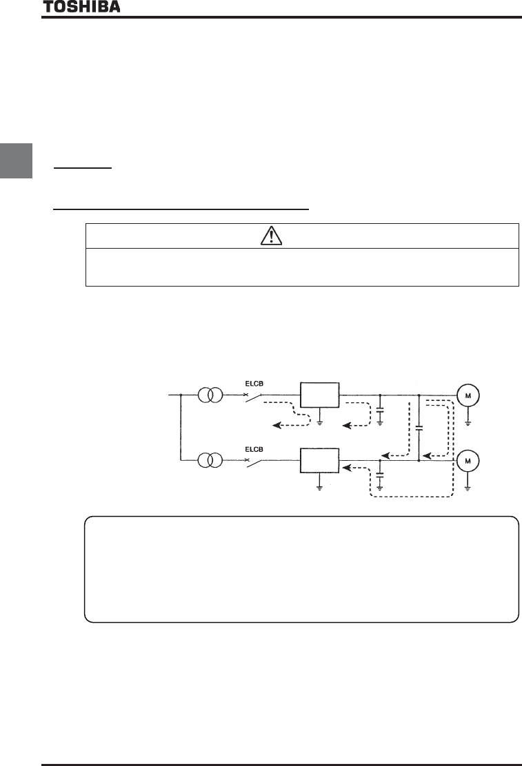
(1) Effects of leakage current across ground
Leakage current may flow not just through the inverter system but also through ground wires to other systems.
Leakage current will cause earth leakage current breakers, leakage current relays, ground relays, fire alarms and
sensors to operate improperly, and it will cause superimposed noise on the CRT screen or display of incorrect current
values during current detection with the CT.
Leakage current path across ground
Power supply
inverter
inverter
Remedies:
There is the following method for reduce leakage current across ground.
1. Reduce PWM carrier frequency.
The setting of PWM carrier frequency is done with the parameter
EH.
2. If there is no radio-frequency interference or similar problem, detach the built-in noise filter capacitor.
Refer to Section 1.3.3. (For inverters of certain capacities, the PWM carrier frequency (EH) must be set
at 4 kHz or below.)
3. Use high frequency remedial products for earth leakage breakers.
If you use equipment like this, there is no need to reduce the PWM carrier frequency.
4. If the sensors and CRT are affected, it can be remedied by reducing the PWM carrier frequency described in
1 above, but if this cannot be remedied because of the increase in the motor's electric magnetic noise,
please consult with your Toshiba distributor.
* Cautions for applying models with a built-in noise filter.
For the models with a built-in noise filter, the leakage current value at power supply of
¨
(delta) connecting wire
(single-phase earth) can be larger than normal inverter, so be careful.
<Standard leakage current value (single-phase earth)>
VFAS1-2004PL~2150PM: Approx. 15mA
VFAS1-2185PM~2450PM: Approx. 1mA