


E6581301
G-10
7
7.3 Setup of external speed command (analog signal)
Function of analog input terminals can be selected from four functions (external potentiometer, 0 to 10Vdc, 4 (0) to
20mAdc, -10 to +10Vdc). The selective function of analog input terminals gives system design flexibility.
Refer to Section 6.28 for fine adjustment of analog setting signal and output frequency.
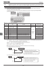
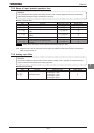
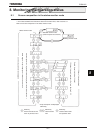
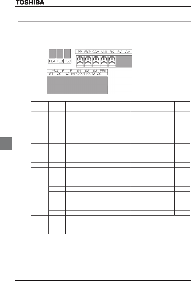
[Control terminal board]
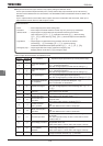
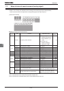
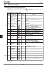
■ Setting of analog input terminal functions
Terminal
symbol
Title Function Adjustment range
Default
setting
- H
Frequency priority selection
:HOQF/H terminal
switching (input terminal
function selection,
)
:HOQF/H
frequency switching
(switch by H)
VI/II
H
VI/II input point 1 setting ~ %
H
VI/II input point 1 frequency ~HJ Hz
H
VI/II input point 2 setting ~ %
CKH
VI/II input point 2 frequency ~HJ Hz *1
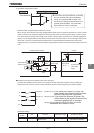
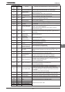
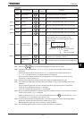
- H
Frequency setting mode selection 2 Same as HOQF
(
~
)
- H
Speed command priority switching frequency ~HJ
All H
Analog input filter (No filter)~ (Max. filter)
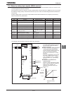
RR/S4
H
RR/S4 input point 1 setting ~ %
H
RR/S4 input point 1 frequency ~HJ Hz
H
RR/S4 input point 2 setting ~ %
CXH
RR/S4 input point 2 frequency ~HJ Hz *1
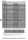
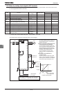
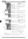
RX
H
RX input point 1 setting -~ %
H
RX input point 1 frequency ~HJ Hz
H
RX input point 2 setting -~ %
H
RX input point 2 frequency ~HJ Hz *1
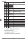
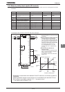
Option
H
~H
AI1, AI2 input point setting
For details, see Instruction Manual
(E6581341) specified in Section 6.41.
H
~H
RP/high speed pulse input point setting
For details, see Instruction Manual
(E6581319) specified in Section 6.41.
*1: Inverter with a model number ending with -WN, HN: 60.0 -WP: 50.0
Note 1: Input terminals of AI1 and AI2 are at expansion TB option unit.
Note 2: Input terminals of RP/high speed pulse is at PG feedback device option unit.