


E6581301
L-4
12
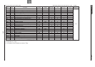
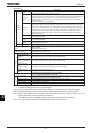
(Continued)
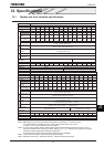
Item
Specification
Display function
4-digit
and
7-segme
nt LED
Alarms
Stall prevention during operation, overload limit, overload, undervoltage on power source side, DC circuit
undervoltage, setting error, in retry, upper limit, lower limit.
Causes of
failures
Overcurrent, overvoltage, overheat, short circuit on the load side, ground fault on the load side, inverter
overload, arm overcurrent at starting, overcurrent on the load side at starting, CPU error, EEPROM error,
RAM error, ROM error, communication error, (dynamic braking resistor overcurrent/overload),
(emergency stop), (undervoltage), (low current), (overtorque), (motor overload), (input phase failure),
(output phase failure)
The items in the parentheses are selectable.
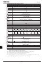
Monitoring
function
Operation frequency, operation frequency command, forward run/reverse run, output current, DC
voltage, output voltage, compensated frequency, terminal board input/output information, CPU version,
past trip history, cumulative operation time, speed feedback, torque, torque command, torque current,
exiting current, PID feedback value, motor overload factor, inverter overload factor, PBR overload factor,
PBR load factor, input power, output power, peak output current, peak DC voltage, RR/S4 input, VI/II
input, RX input, AI1 input, AI2 input, FM output, AM output, expansion I/O card option CPU version,
integral input power, integral output power, communication option reception counter, communication
option abnormal counter
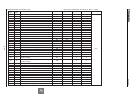
Free unit display
Display of optional units other than output frequency (motor speed, line speed, etc), current ampere/%
switch, voltage volt/% switch
Automatic edit
function
Searches automatically parameters that are different from the standard default setting parameters. Easy
to find changed parameters.
User default
setting
User parameter settings can be saved as default settings. Allows to reset the parameters to the
user-defined parameter settings.
LED Charge display Displays main circuit capacitor charging.
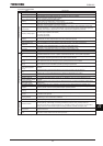
Input/output terminal input
function
Possible to select positive logic or negative logic with programmable input/output terminal function menu.
[Note 1] [Note 2]
(Default setting: positive logic)
Sink/source switching
Possible to switch between minus common (CC) and plus common (P24) for control terminal.
(Default setting: minus common (CC))
output signal
Failure detection signal 1c contact output (250Vac-2A-cosɎ=1, 250Vac-1A-cosɎ=0.4, 30Vdc-1A)
Low speed/speed reach
signal output
[Note 2]
Open collector output (24Vdc, max. 50mA, output impedance: 33)
Upper/lower limit
frequency signal output
[Note 2]
Open collector output (24Vdc, max. 50mA, output impedance: 33)
Output for frequency
meter/
Output for ammeter
[Note 3]
Analog output. 1mAdc full-scale DC ammeter or 7.5Vdc-1mA voltmeter
Pulse train frequency
output
Open collector output (24Vdc, max. 50mA)
Communication function
RS-485 standard 2-channel equipped (connector: modular 8P)
CC-Link, DeviceNet and PROFIBUS-DP are optional.
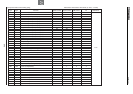
Environments
Use environments Indoor use. Altitude: 3000m or less (current reduction necessary if 1000m or more.) Place not exposed
to direct sunlight and free of corrosive and explosive gases.
Ambient temperature -10 to +60°C (Remove the upper c over if 40°C or more, max. 60°C) [Note 4]
Storage temperature -25 to +70°C
Relative humidity 20 to 93% (free from condensation)
Vibration 5.9m/s
2
{0.6G} or less (10 to 55Hz) (Compliant with JIS C60068-2-6)
Note 1: 16 contact input terminals (of which 8 are options) are programmable contact input terminals, and they make
it possible to arbitrarily select from 114 types of signals.
Note 2: Programmable ON/OFF output terminals make it possible to arbitrarily select from 168 types of signals.
Note 3: Programmable analog output terminals make it possible to arbitrarily select from 54 types of signals.
Note 4: When using inverters where the ambient temperature will rise above 50°C, remove the upper cover and
operate each inverter at a current lower than the rated one.
(200V-55kW or lager and 400V-90kW or larger models dose not need remove the upper cover)
Note 5: This function protects inverters from overcurrent due to output circuit ground fault.