


E6581301
M-4
13
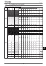
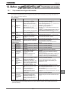
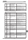
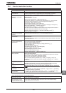
(Continued)
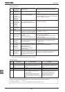
Error
code
Description Possible causes Remedies
GVP
Motor constant
setting error
Some items indicated on the motor
nameplate are not entered correctly.
•Base frequency WN
•Base frequency voltage 1 XNX
•Motor rated capacity H
•Motor rated current H
•
Motor rated speed
H
•
Make sure that all i
tems on the motor nameplate
are entered correctly.
GV[R
Inverter type
error
•Is circuit board (or main
circuit/drive circuit board)
replaced?
•When board has been replaced, input
for
V[R.
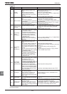
G
Analog input
terminal
overvoltage
•
Overrated voltage is app
lied to
analog input.
•
Apply voltage within the rated voltage.
G
Sequence error
•The signal from system is not
inputted into input terminals.
•The input terminal function (,
) is not set up.
•A value other than 0.0 is specified
for H, although the brake
answer function is not used.
•Please check if the sequence is normal or not.
•Please set or as the input terminal to
use.
•Please set up 0.0, when you do not use
system-supporting sequence.
G
Encoder error
•Disconnection of encoder circuit.
•The encoder is not connected
correctly.
•Check connection of encoder.
Connect encoder correctly.
•Check whether the setting of H matches the
phase-A and phase-B connections of the encoder.
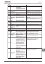
G
Speed error
(Over speed)
•Speed error (Inverter error,
Encoder error)
•The deceleration time FGE is too short.
•Over speed by overvoltage limit
operation
•Using braking function in not
connect a motor
•Check the setting of H ~ H
•Check connection of encoder.
•Increase the deceleration time FGE.
•In the case of overvoltage limit operation, install a
dynamic braking resistor or increase the
deceleration time FGE.
•Operation in connect a motor.
G
Terminal input
error
•Braking down of a wire for VI/II
input signal.
•Terminal circuit board comes off
and falls
•P24 overcurrent
•Check VI/II input signal.
•Install the control terminal board to the inverter.
•Check P24 terminal short circuit to CC or CCA.
G
Abnormal
CPU2
communication
•An error arises during CPU2
communication.
•Contact your Toshiba distributor.
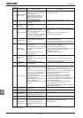
G
V/f control error
• Output voltage / Output frequency
ratio is too high compared to motor
rating.
• It was run in vector control mode
(RV=,,, or ) without
setting parameters (Auto-tuning)
concerning the motor.
• Motor was in over-excitation state
during deceleration.
• Motor constant 1 (Torque boost)
H is too large.
• Motor was started under the brake
closed.
• Set Base frequency voltage 1 XNX and Base
frequency XN in accordance with motor rating.
• When operating a motor in V/f control mode
selection RV=,,, or , follow section 6.22,
and then set the parameters (Auto-tuning)
concerning the motor.
• If the inverter is tripped during deceleration
because of V/f control error (G) when
H (Over voltage limit operation) is set to 2 or
3, decrease the value for H (Regenerative
over-excitation upper limit)..
• If the inverter is tripped during low frequency,
decrease the value for H.
• If the inverter is tripped during braking, make the
brake release timing early.
G
CPU1 fault
•A software error occurs in the
control CPU.
•Contact your Toshiba distributor.
G
Abnormal logic
input voltage
•An abnormal voltage is applied to
the control logic input terminal.
•Check the signal given to the logic connected with
the input terminal.
G
Option 1 error
•Option card 1 is defective.
(Installed option at lower side)
•Contact your Toshiba distributor.
G
Option 2 error
•Option card 2 is defective.
(Installed option at upper side)
•Contact your Toshiba distributor.
G
Stop position
retaining error
•A deviation error occurs during
stop position retaining control.
•The stop position adjustment
range specified with H is too
narrow.
•Creeping speed is too fast.
•Check connection of encoder.
•Adjust the proportional P gain H.
•Increase H.
•Lower the creeping speed.
(Continued overleaf)