


E6581301
F-35
6
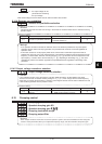
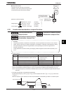
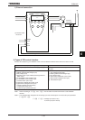
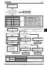
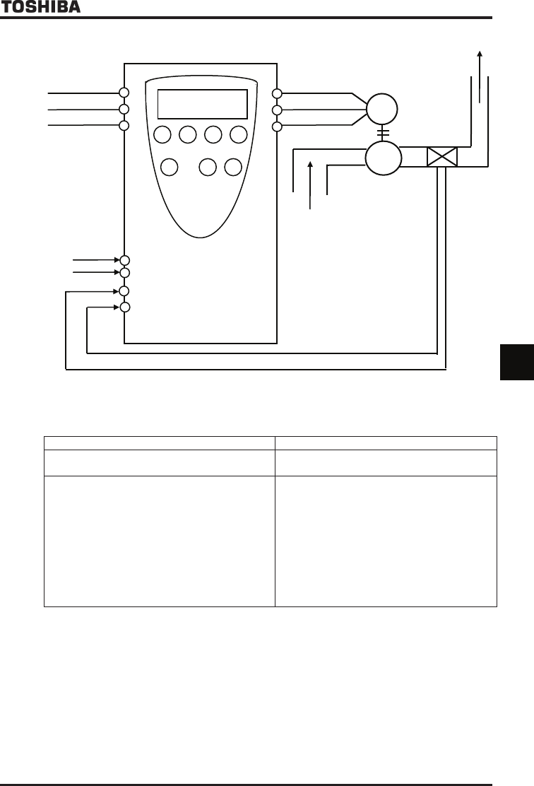
1) External connection
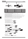
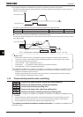
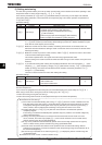
2) Types of PID control interface
Process value (frequency) and feedback value can be combined as follows for the PID control of the VF-AS1.
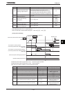
(1)Process value(frequency setting) (2) Feedback value
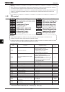
Frequency setting mode selection HOQFᲩH PID control feedback control signal selection
H
:VI/II (voltage/current input)
:RR/S4 (potentiometer/voltage input)
:RX (voltage input)
:Operation panel input enabled (including LED/LCD
option input)
:2-wire RS485 communication input
:4-wire RS485 communication input
:Communication option input
:Optional AI1 (differential current input)
:Optional AI2 (voltage/current input)
:Motor operated pot mop setting
:Optional RP pulse input
:Optional high-speed pulse input
:Deviation input (no feedback input)
:VI/II (voltage/current input)
:RR/S4 (potentiometer/voltage input)
:RX (voltage input)
:Optional AI1 (differential current input)
:Optional AI2 (voltage/current input)
: PG feedback option
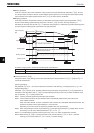
Note 1: About the setting of ¢HOQFandH: Do not select the same terminal that is used feedback
terminal.
Note 2: The voltage/current changeover of the analog input VI/II and the option AI1 can be set by the parameter
H or H
HᲦH 0:Voltage input (DC:0~10V)
1:current input (DC:4~20mA)
R
S
T
U
V
W
Pressure
transmitter
M
P
(2) Feedback value DC:4~20mA
(1) Process value
DC:0~10V
RR/S4
CCA
VI/II
CCA